Our Brands

My Documents 0

Welcome to the ASCO Website

Welcome to our website.

Timing Delays for ATS Transition Modes

Timing Delays play an important role in the operations of transfer switches in backup power systems. This document briefly summarizes common transition modes for Automatic Transfer Switches (ATS), identifies timing delays that are typically available on transfer switches, and describes delays that are specific to certain ATS transition modes.

TRANSITION MODES

The most common transition modes are open, delayed, and closed transition sequences. Each is explained in the following sections. For additional detail, review Part 1 and Part 2 of the ASCO document entitled Transition Modes for Automatic Transfer Switches.

Open Transition

The simplest transition mode is Open Transition, which uses a “break-before-make” transition sequence. It is widely used in mixed load applications. Figure 1 shows the voltage output of an ATS that employs an open transition switching sequence.
Delayed Transition

Delayed Transition is similar to open transition in that there is an interruption between breaking the contacts for one power sources and closing on the contacts for the alternate power source. However, the amount of time between these operations is typically adjustable. Figure 2 illustrates the sequence. Delayed Transition is often used to avoid inrush currents associated with transferring motor loads between power sources.
Closed Transition

Closed Transition transfer switches momentarily overlap the contacts for each power source during each transfer. This results in a transfer without even an instantaneous power interruption, as shown in Figure 3.

THE ROLES OF DELAYS

In a prior Tech Brief, ASCO Power Technologies described the roles of essential time delays invoked during a load transfer cycle between two power sources. The following sections describe elements of those delays and how they are used to avoid nuisance transfers in backup power systems.

Avoiding Unnecessary Transfers

When deciding whether to transfer power, it is important to avoid switching activity that may actually be unnecessary. That is because transfers can result in (depending on power system configuration) momentary power disruptions that affect sensitive loads and their operations. Unnecessary transfers also result in unnecessary wear-and-tear on electrical equipment and unnecessary operating costs for engine-generator sets. Avoiding nuisance switching is the best way to avoid these effects.

Assessing Stability of a Normal Power Source

An ATS continually monitors its connected power source to verify acceptable voltage and frequency. If an ATS controller detects an absence of voltage on the normal source, the ATS controller initiates a series of operations to transfer electrical load to the emergency power source. The following sections describe delays commonly used to optimize transfer operations. (For more information, review the ASCO document entitled Basic Control of Automatic Transfer Switches.)

COMMON DELAYS

The following delays are typically available on ATS, regardless of transition type.

Source Failure Delays

Transfer switches monitor source voltage and frequency, and can detect aberrations quickly. If a normal source exhibits unacceptable aberrations for a very short interval, a transfer switch signals a genset to start, initiates load transfer when the genset produces acceptable power, then retransfers to the normal source after that source again evidences stability. If the transient condition was immaterial to the facility operation, the switching cycle was unnecessary. If open transition transfer switching is used, the switching cycle unnecessarily introduced two very brief power interruptions. If this occurs often, the cumulative effects of switching activity could be excessively disruptive.

Nuisance switching from Normal-to-Emergency can be avoided by delaying the issuance of the engine start signal. Persistence of an unacceptable power condition until the delay interval expires confirms the necessity for transfer and typically results in signaling a genset to start. Such delays allow overcurrent protection devices to clear faults, if any.

For commercial applications, a typical Source Failure Delay value is 3 seconds. For life safety loads, this delay is often set to zero. The maximum duration of this interval is limited by availability of ride-through power for a transfer switch’s controller. For this reason, manufacturers offer transfer switches with a ride-through power capability. The duration of ride-through power can vary between models and manufacturers.

Normal-to-Emergency and Emergency-to-Normal Transfer Delays

Normal-to-emergency transfer delays are especially useful where power is distributed through more than one transfer switch. Delays can be staggered across generator transfer switches to avoid block loading on the generator, where the entire emergency load is placed on the alternate power source in a single instant. This delay is also used to provide additional time for generators to develop speed and stabilize. When power returns to the normal source, an Emergency-to-Normal Transfer Delay ensures that power is stable on the normal source before switching load to it. This delay begins when the generator voltage and frequency rise beyond pickup thresholds.

Retransfer-to-Normal Delays

For outages, it can be important to ensure that a normal source is stable before load is reconnected to it, whereas a post-test retransfer occurs between two stable power sources. For this reason, separate retransfer settings can be available for retransfers following outages and tests. Longer delays are used following outages to verify stability, while shorter delays are used following tests because both power sources are already stable.

Engine Cooldown Delay

A basic transfer cycle finishes after load is retransferred to normal and the ATS controller initiates an Engine Cooldown Delay. Engine manufacturers recommend cooldown run-times, which can be especially important for avoiding deleterious conditions in gensets, for example, those powered by turbocharged diesels. Typical values for this delay can be 10 to 15 minutes. Figure 4 illustrates the sequences of events and basic delays in a typical transfer cycle.

Pre-Transfer and Post-Transfer Delays

For some motor and inductive load applications, it is necessary to avoid or reduce inrush current during load transfer to prevent operational disruptions or damage to equipment. As a result, some facilities employ control circuits that disconnect specific equipment, such as motors, prior to transfer, then separately reconnect the equipment after the transfer is completed. Often, these delays are used in conjunction with test events, but not in conjunction with power outages. A diagram of a motor control disconnect circuit is shown in Figure 5.
Pre- and Post-Transfer Delays are available for Normal-to-Emergency and Emergency-to-Normal transfers. A bypass feature for the Normal-to-Emergency can be employed should the emergency source fail while connected to the power distribution system.

For additional approaches for transferring motor loads, review the ASCO Power Technologies document entitled Transferring Motor Loads Between Power Sources.

Inphase Transfer Delay

Controllers for ATS monitor voltage and frequency. Some are also configured to compare phase angle differences between sources, then close on an alternate power source only when the phase angle difference is within acceptable limits. This approach mitigates inrush currents attributable to phase angle difference between power sources. Inphase Transfer Delays are used to set the maximum time for passive phase angle synchronization. If the delay expires, then the controller abandons phase angle synchronization or the switch remains connected to the existing power source.

Commit to Transfer Setting

While the rest of this document addresses delays, there is a relevant transfer switch setting that should be considered when evaluating a delay strategy. A Commit to Transfer Setting addresses what a transfer switch controller should do if the triggering aberration on the power source resolves before a transfer is complete. Its function is best explained by example.

Following an unacceptable voltage reduction, a controller initiates a series of events and delays in preparation for transfer to the alternate power source. While that is happening, voltage on the original source returns to the acceptable range. Should the transfer be completed? Doing so assures connection to a stable power source, but could ultimately be unnecessary if the original power source will actually be stable. Likewise, aborting the transfer avoids potential disruption, wear, and fuel costs incurred by engaging backup power, but could leave the power distribution system connected to a source whose stability is unverified. The Commit to Transfer Setting enables the selection of a default strategy for this circumstance.

DELAYS FOR DELAYED TRANSITION SEQUENCES

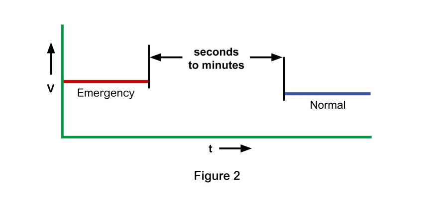
As previously explained and illustrated in Figure 2, Delayed Transition Transfer Switches use break-before-make switching to temporarily depower circuits, allowing motor and inductive loads to decay. The amount of time between breaking and making the respective contacts is typically selectable and can range from seconds to minutes. The Delayed Transition Time Delay is the setting that specifies this variable. The duration is usually determined by an engineer’s assessment of the connected loads and their decay times.

DELAYS FOR CLOSED TRANSITION SEQUENCES

Failure to Sync Delay

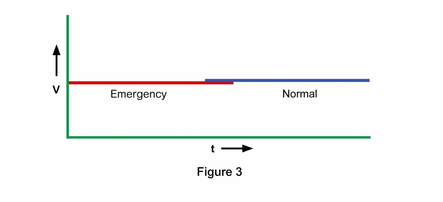
As previously explained and shown in Figure 3, Closed Transition Transfer Switches momentarily overlap the contacts for each power source during each transfer to avoid power transients. In doing so, the switch controller monitors differences in voltage, frequency, and phase angle to verify passive synchronization between the two power sources. The Failure to Synch Delay specifies the maximum amount of time for allowing passive synchronization to occur. If the delay expires, then the controller abandons the transfer and the switch remains connected to the existing power source, or changes to a delayed transition sequence.

Extended Parallel Alarm

Closed transition sequences must limit normal and emergency contact overlap to protect equipment and avoid safety risks. If a switch malfunctions, the Extended Parallel Alarm Delay specifies the maximum elapsed time that both normal and emergency contacts can simultaneously remain closed. When this delay expires, alarm contacts change state, the transfer switch controller is bypassed, and an output trips an upstream breaker for one of the power sources to terminate parallel operation. This feature can be set to open either the normal or emergency source breaker.

SUMMARY

The following table summarizes the automatic transfer switch delays described herein. For additional information, contact an ASCO Power Technologies representative.

Table 2: Select UL 50 Enclosure Types

Delay
Description
Function
Typical Value
Common Delays
Source Failure Delays
Override Momentary Normal Source Outages Delays nuisance retransfer to normal for short duration transient conditions Avoids most nuisance transfers due to transient events ~3 Seconds
Override Momentary Emergency Source Outages Delays nuisance retransfer to normal for short duration transient conditions Avoids most nuisance transfers due to transient events ~3 Seconds
Transfer to Emergency Delays transfer to emergency for a prescribed interval Allows generators to stabilize beyond pickup voltage, and can stagger multiple ATS to avoid block loading ~5-30 Seconds
Engine Cooldown Following loaded operation, allows engine to operate unloaded Allows engine to cool in accordance with manufacturer recommendations ~10-15 Minutes
Retransfer to Normal if Normal Fails Delays transfer back to normal source following transfer to emergency Ensures stability of normal source before retransfer ~30 Minutes
Retransfer to Normal During Test Event Delays retransfer following transfer to emergency Ensures stability of normal source before retransfer and sets test runtime ~5 Minutes
Normal to Emergency Pre-Transfer signal Sends output signal notifying other equipment of pending transfer Enables equipment to be depowered before transfer ~5 Seconds
Normal to Emergency Post-Transfer Signal Sends output signal notifying other equipment of completed transfer Enables equipment to be depowered after transfer ~5 Seconds
Emergency to Normal Pre-Trnasfer Signal Sends output signal notifying other equipment of pending transfer Enables equipment to be disconnected before transfer ~5 Seconds
Emergency to Normal Post-Transfer Signal Sends output signal notifying other equipment of completed transfer Enables equipment to be disconnected before transfer ~5 Seconds
Closed Transition Delays
Failure to Synchronize Maximum elapsed time for attempting to synchronize two power sources for transfer Issues alarm. Controller can be set to invoke a delayed transition sequence. ~5 Minutes
Extended Parallel Time Maximum elapsed time that both normal and emergency contacts can simultaneously remain closed Alarm issued, issues signal to upstream breaker to trip open. 100 Milliseconds
Delayed Transition Delays
Delay Transition Time Amount of time when both normal and emergency contacts remain disconnected This setting specifies how long motors and inductive loads will decay before reconnection ~3 Seconds to 2 Minutes

Read related articles

Children learning

Microgrid for a Children’s Home Puerto Rico, USA

A children's home in Puerto Rico endured a prolonged power outage for months after Hurricane Maria. This ASCO Power case study details how a microgrid solution restored power and drove power resilience.
Two people wearing hard hat discussing while looking at the laptop

Transfer Mechanism Basics

The central component of every power transfer switch is its switching mechanism. This document explains the essential components in ASCO Power transfer switches.
IT professional working at a server room

Transferring Loads with Zero Power Interruption

This document describes the operation and benefits of using transfer switches that operate without disrupting the flow of power to loads.
Two people wearing hard hat looking at some designs on paper

Benefits of Custom-Engineered Transfer Switches

Custom-engineered transfer switches can save space, time, labor, and overall cost. Learn more about these benefits in this document.