Commercial facilities offer a space for economic activities such as office, retail, entertainment, and dining. Selective coordination offers a way to minimize the impact of outages with the use of overcurrent protection devices and critical power equipment that support it. It helps provide continuous power to life safety loads, minimize downtime, and reduce arc flash hazards.
This document defines the concept and provides guidance on specifying automatic transfer switches rated for this strategy.
Problems in Uncoordinated Power Distribution Systems
In a power distribution system equipped with multiple levels of overcurrent protection devices, circuit breakers or fuses are installed in primary, secondary, and tertiary distribution circuits. If a fault occurs far from the primary distribution panel in an uncoordinated system (a system using devices with similar trip times), it is possible that an overcurrent protection device could open far upstream of the fault location, as shown in Figure 1.
The tripped breaker would disconnect power to an unnecessarily large portion of a facility. This could cause downtime for different wings of the building, causing interruptions to more stores. Employing a selective coordination strategy helps avoid this.
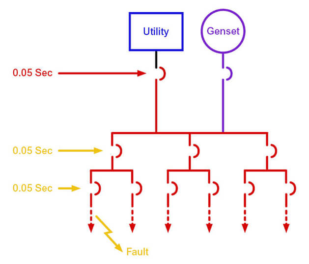 Figure 1
In an uncoordinated system, a breaker in an upstream panel may trip before downstream breakers, resulting in power loss for a large number of loads.
Selective Coordination Defined
Selective Coordination is an approach where the opening times of overcurrent protection devices are specified so that the fuses or breakers located closest to faults open first. Article 100 of the
2020 National Electrical Code® (NEC
®) provides a more formal definition for Selective Coordination:
Localization of an overcurrent condition to restrict outages to the circuit or equipment affected, accomplished by the selection and installation of overcurrent protective devices and their ratings or settings for the full range of available overcurrents, from overload to the available fault current, and for the full range of overcurrent protective device opening times associated with those overcurrents.1
By installing overcurrent protection devices with sequential trip times, designers can ensure that the protective device located nearest to a fault will trip first. This interrupts power to fewer loads, which is less disruptive to the operations in the building. Figure 2 shows the local isolation of a fault in a system where opening times have been selectively coordinated across the power distribution system.
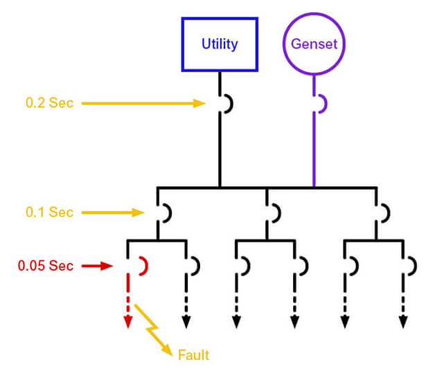 Figure 2
By selectively coordinating breaker trip times, faults can be isolated to the loads furthest downstream, minimizing impact to the remainder of a facility.
Differences Between Overcurrent Protection Devices and Transfer Switches
In a fused circuit, a fuse opens when subjected to an overcurrent for a prescribed duration. When a very large overcurrent reaches switched mechanisms such as circuit breakers and ATSs, strong magnetic forces attempt to push their contacts apart, which could open the circuit. To understand the potential impact, it is important to recall the essential purposes of both the overcurrent protection devices and automatic transfer switches.
The primary function of overcurrent protection devices is to disconnect power sources from downstream circuits and loads to avoid unsafe conditions and resulting damage. However, the power switching contacts in a
transfer switch must remain closed when overcurrents occur (up to the ratings of the device) until an overcurrent protection device clears the circuit. This allows downstream overcurrent protection devices to work as designed, including any provisions for selective coordination.
NEC Provisions Regarding Selective Coordination
| Table 1. NEC Selective Coordination Requirements |
| Article |
Application |
Requirement |
| 517 |
Healthcare Facilities |
517.26 |
| 620 |
Elevators/Escalators |
620.62 |
| 645 |
IT/Data Systems |
645.27 |
| 695 |
Fire Pumps |
695.3(C)(3) |
| 700 |
Emergency Systems |
700.10(B)(5)(b)(ii); 700.32 |
| 701 |
Legally Required Standby Systems |
701.32 |
| 708 |
Critical Operations Power Systems |
708.54 |
|
UL 1008 Ratings
As noted, large fault currents generate magnetic forces that attempt to open switch contacts. If an ATS were to transfer load to an alternate power source during a fault, it must be able to close on and hold that current to avoid power interruption. In addition, large fault currents passing across transfer switching contacts generate heat that can degrade contact materials and surfaces.
To become UL 1008 Listed, transfer switches must undergo testing by Underwriters Laboratories or a UL-approved lab to evaluate the amounts of fault current they can withstand and close on for durations specified in the standard or any optional durations specified on the manufacturer’s label. The resulting ratings are known as Withstand and Close-On Ratings, or WCRs.
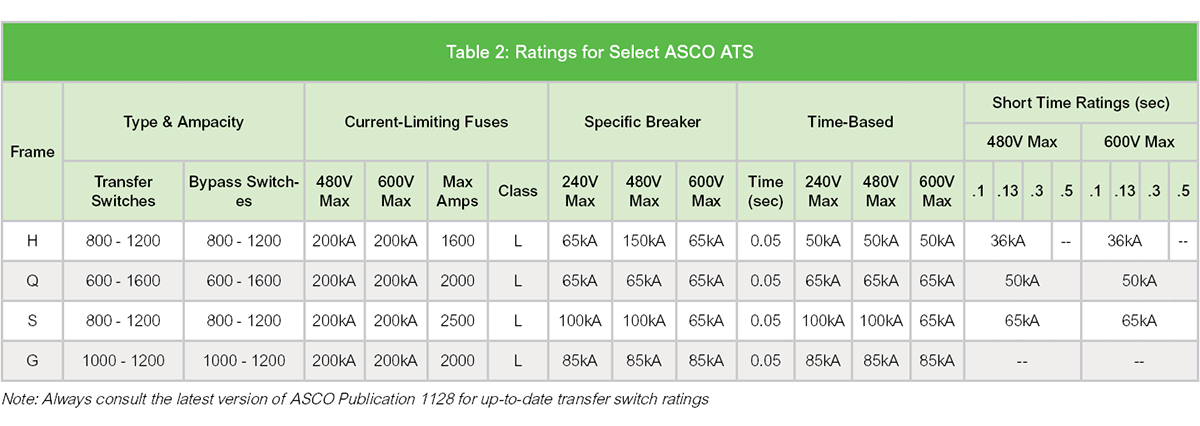
There is an inverse relationship between the amount of fault current that a transfer switch can handle and the duration it can be held, as shown in Figure 3. Different types of overcurrent protection devices offer differing clearing times. Consequently, an ATS will typically be assigned multiple ratings according to the types of upstream protection that can be used. Example ratings from ASCO transfer switches are shown in Table 2.
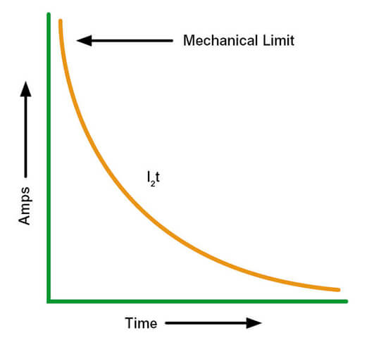 Figure 3
There is an inverse relationship between the current an ATS can withstand and the duration for which it can be held.
Because current-limiting fuses open most quickly and also limit the peak fault current, they provide the highest WCRs for a specific transfer switch. Manufacturers also list maximum test values for use with specific circuit breakers. Because these typically open less quickly, the associated values are usually lower than those for fuses.
In addition, manufacturers specify values for coordinating the ATS with circuit breakers other than the specific models of breaker that were used during transfer switch testing. Because these optional ratings are associated with a 0.025 or 0.05-second test time interval, they are known as Time Based Ratings. Manufacturers also have the option of testing switches for longer intervals, and UL 1008 suggests durations of 0.1, 0.13, 0.3, and 0.5 seconds. The resulting values are known as Short Time Ratings. Each type of rating is shown for select ASCO transfer switches in Table 2 above.
Required Information
Settings for overcurrent protection devices are usually specified following the completion of a coordination study of a building’s power distribution system. Among other parameters, coordination studies evaluate the amount of fault current that could reach various locations throughout the power distribution system. To selectively coordinate the protective devices, engineers then select overcurrent protection settings that will cause downstream breakers to trip before upstream units. As noted, a transfer switch must hold the anticipated current to prevent inadvertent power outages to loads until protective devices clear the circuit.
To select the most appropriate ATS, the overcurrent protection devices should be known and the results of a completed selective coordination study should be available. At that point, the information needed to select an ATS includes (1) the nominal voltage and amperage of the load, (2) the maximum fault current that will be available at key locations, and (3) the duration for which a transfer switch must hold this current. By comparing this information to transfer switch specifications, an appropriate model can be selected. The WCRs and Short Time Ratings of the transfer switch must equal or exceed the above-referenced values.
In some applications, specifiers might consider using transfer switches that can hold current for longer durations than required by the coordination study. This practice offers additional flexibility for selective coordination, particularly when plans for further power system improvements are unclear. However, higher-rated transfer switches typically weigh more (making installation more labor-intensive and costly), occupy additional space, and have higher purchase costs. In addition, holding circuits closed for a longer duration increases downstream incident energies. This can present additional risk to personnel, and thus affect how equipment can be serviced. Consequently, minimizing opening time differences between overcurrent protection tiers can avoid unnecessary logistics and costs. Figure 4 shows a 30-cycle transfer switch. Coordination schemes with and without 0.5-second switches are compared in Figure 5.
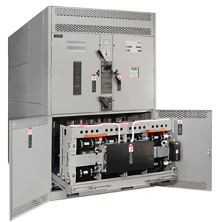 Figure 4
An ASCO U-frame switch can hold 100kA currents for 0.5 seconds.
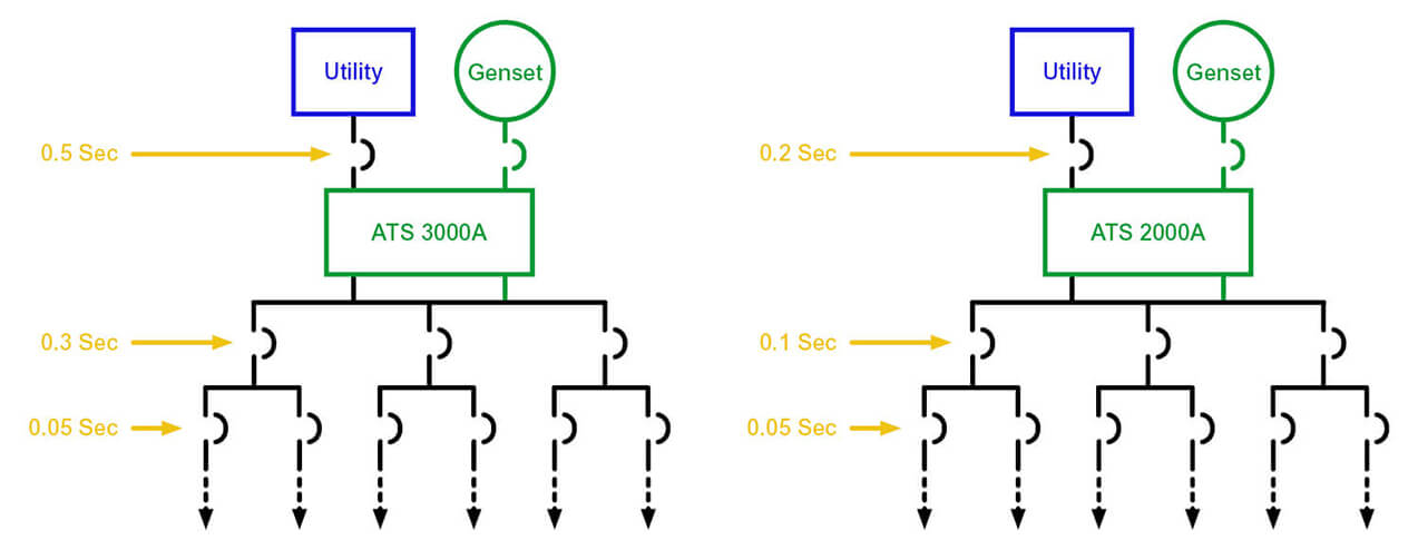 Figure 5
Both systems may provide effective selective coordination, but the system at right achieves this objective without the additional cost of a potentially larger 0.5-second switch.
Summary
Selective coordination strategies minimize the number of loads that will be de-energized if a fuse or breaker opens. These strategies cause overcurrent protection devices nearest to faults to trip first, avoiding power disruption to a greater amount of load equipment. This is valuable to commercial facilities where uptime is critical to maintaining business operations and meeting consumer expectations.
In a retail facility, it could enable an electrical system to clear a fault in a branch load circuit without depowering nearby point-of sale equipment, enabling a retailer to keep operating. In an office building, selective coordination could be used to limit an HVAC distribution system fault to a smaller area, sparing any data closet or server room on the same cooling system from an HVAC outage that could disrupt office operations.
1 National Fire Protection Association. NFPA 70, National Electrical Code®. 2020 Edition. Article 100. p. 70-34.