Our Brands

My Documents 0

Welcome to the ASCO Website

Welcome to our website.

UL 1008 Transfer Switch Withstand and Closing Ratings

Quick Summary:

UL 1008 – Standard for Safety – Transfer Switch Equipment is the leading transfer switch testing standard for the North, Central, and South American markets. UL 1008 specifies robust testing requirements for verifying manufacturer ratings, including Withstand and Closing Ratings. This document describes the need for Withstand and Closing Ratings and summarizes key UL 1008 tests used to verify them.

Use this information on Transfer Switch Withstand and Closing Ratings to:
  • Learn the purpose of Transfer Switches
  • Understand the need to withstand and close on fault currents
  • Know the value of UL 1008 Transfer Switch Qualification Testing

What is a transfer switch?

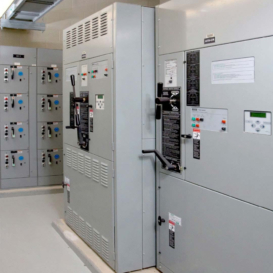
As their name implies, transfer switches connect electrical loads to one of two sources of power. These sources are typically dissimilar, such as alternating current applications with power feeds from a public utility and an on-site generator. While the purpose of a transfer switch seems clear, it is important to distinguish it from the purpose of an overcurrent protection device (OPD).

The purpose of a transfer switch is to connect electrical load to an alternate power source when the normal source is unacceptable. As a result, a transfer switch connected to a power source must withstand and close on short-circuit currents until they are cleared by an OPD. Thereafter, a transfer switch must remain operable so that it can connect to the alternate source.

In contrast, the purpose of an OPD is to open a circuit to protect equipment and mitigate hazards arising from overcurrent conditions. As a result, an OPD must be capable of disconnecting power sources from loads when faults occur.

ADDITIONAL FUNCTIONS OF AN AUTOMATIC TRANSFER SWITCH

In addition to carrying current continuously, an Automatic Transfer Switch (ATS) must reliably perform the following functions when conducting current from a normal source:

1. Detect Power Failures – To respond to a power outage or aberration on a normal power source, the condition must be detected.
2. Sense the Acceptability of the Alternate Source – If the alternate source is an auxiliary generator, it must be started to provide the necessary current, which must be monitored to ascertain acceptability.
3. Transfer Load – With certain exceptions, an ATS transfer mechanism must disconnect from and isolate the normal source before connecting to an alternate source.
4. Sense the Restoration of the Normal Source – The voltage and frequency of the normal source must be within prescribed limits before load can be transferred to it. In some applications, phase angle differences between the sources must also be within an acceptable range. ATS must assess these characteristics as a prerequisite to load re-transfer.
5. Re-Transfer Load to the Normal Source – An ATS must reliably transfer loads to the normal source. ATS can employ one of several transfer sequences according to the needs of specific applications, including, open, delayed, closed, and soft-load transition sequences. Read Part 1 and Part 2 of our paper entitled Transition Modes for Automatic Transfer Switches for additional information.


THE NEED TO WITHSTAND AND CLOSE ON FAULT CURRENTS

The duration for which a transfer switch can withstand a short circuit current is inversely proportional to the amount of current that must be tolerated, as shown in Figure 1. An ATS must be able to withstand and close-on foreseeable fault currents until cleared by an OPD. The following sections describe why.
Withstanding Faults

When a fault occurs, it should be cleared by the upstream OPD closest to the fault location. Referring to Figure 2, a fault occurring at Point A should be cleared by Feeder Breaker F3. If Main Breaker M were opened, the fault would be effectively cleared. However, this would also de-energize loads on circuits unaffected by the fault (F1, F2) and result in an unnecessarily large impact on facility operations.

Likewise, referencing Figure 3, a fault occurring at Point B should be cleared by Breaker L1, and not by Breaker F3. While the latter would clear the fault, it would also unnecessarily de-energize all loads on circuits fed by Breakers L2 and L3. If the transfer switch opened instead, an unnecessary amount of loads would again be de-energized.
To ensure that faults will be cleared by the breaker closest to a fault location, trip settings must be assigned to breakers following the completion of a coordination study of the power distribution system. This study should identify the amount of fault current that will be available at each OPD and generator transfer switch location so that appropriate time delays can be applied to upstream and downstream OPDs. The practice of applying sequential trip delays to OPDs to limit impact of outages is known as selective coordination. For more information about this practice, review our document entitled Selective Coordination Basics.

After short-circuit current testing, a transfer switch must remain in a condition to connect loads to sources. The UL 1008 standard prescribes criteria for post-test condition of the switch.

Closing on Faults

Transfer mechanisms must not only withstand faults but close on them as well. A primary reason is that a switch may be retransferred to a live power source while a fault is still present. The switch must be able to close on foreseeable faults so that, again, OCP devices can properly clear them. If the transfer switch cannot close, all the downstream loads will remain without power, instead of the loads on only the faulted circuit.

UL 1008 TRANSFER SWITCH QUALIFICATION TESTING

The capability to handle fault currents is verified by testing a transfer switch according to UL 1008 – Transfer Switch Equipment. This standard specifies testing criteria for confirming Withstand and Closing Ratings. Transfer switches become UL-Listed after a manufacturer submits documentation of successful testing at rated capacity according to UL 1008 requirements. The National Electrical Code® requires the installation of UL-Listed transfer switches, and inspectors verify compliance by evaluating UL labels on installed ATS units. UL 1008 requires ATS samples to be tested for operability, overload, endurance, short-circuit current handling capability, and temperature rise. The following sections focus on those tests associated with establishing Withstand and Closing Ratings.

Required Tests

To demonstrate withstand capability, transfer switches must carry prescribed amounts of current for prescribed durations. The current requirements scale with the ampacity of the transfer switch, as shown in Table 1.1 The test is initiated with the contact-under-test already closed.
To demonstrate acceptable performance, UL 1008 requires that the sample transfer switch evidence certain capabilities and conditions. These include:

• ability to close on untested contacts of the opposite power source circuit
• ability to operate using whatever automatic or manual controls are provided
• no continuity between the terminals of the normal and alternate power source circuits
• no opening of doors on transfer switch enclosures
• cables cannot pull away from lugs and connectors

Withstand Test

For the Withstand Test, current must pass through the transfer switch until the OPD (fuse or breaker) opens. An optional time-based test may also be conducted to provide additional short circuit ratings for a minimum of 0.050 seconds.2 Shorter durations may be used for switches rated 400 Amps or less, provided their labels are marked in accordance with specific UL 1008 provisions.3 Power factor must not exceed 0.50 for currents up to 10000 Amps, 0.30 for currents up to 20000 Amps, and 0.20 for currents exceeding 20000 Amps4.

Closing Test

A transfer switch must be able to close on contacts when the transfer switch is subject to the same conditions that occur under withstand testing. To demonstrate close-on capability, the Closing Test is conducted using the same switch and contacts that were used in the Withstand Test. The Closing Test is initiated with the contacts-under-test in the open position, which is then closed on an energized source circuit. The test current is the same used in the Withstand Test. The passing criteria are the same for both tests.

Dielectric Voltage Withstand Test

Following the Withstand and Closing Tests, UL 1008 requires the same ATS be subjected to a Dielectric Voltage Withstand Test to verify circuit isolation. This is performed using the same contacts used in the prior tests. This test must apply “twice the rated voltage [of the ATS] but not less than 900V.”5 The standard lists six types of locations where voltage must be measured to demonstrate circuit isolation as well as the alternating current frequencies that must be used.

Considerations for Withstand and Closing Rating Results

Fused Circuits Provide Highest Short-Circuit Current Ratings

Supply circuits may be equipped with any of several types of OPDs, including fuses, molded case circuit breakers, and power breakers. Because fuses open most quickly, their use typically provides the highest short-circuit current carrying capabilities. When using other OPD types, the transfer switch must withstand faults for longer durations, resulting in lower short-circuit current ratings. ATS must be tested with each type of OPD to carry a corresponding rating.

Benefit of Providing Both “Time-Based” and “Specific Breaker” Ratings

UL 1008 requires manufacturers to specify the maximum amount of current that can pass through the transfer switch when it is protected by a generic, unspecified circuit breaker. Using this rating, an end-user can install any circuit breaker provided that it opens within the time specified on the short-circuit current rating labelled on the transfer switch.

UL 1008 offers an opportunity to rate a switch by testing it with specific breakers installed. If a specific make and model of breaker remains closed on currents exceeding its “Time-Based” rating, a transfer switch may be tested and listed for use at the higher amperage with the specific breaker that was tested. For manufacturers, this allows listing switches at higher fault ampacities with specific breakers but requires (1) that testing be repeated with every specific breaker they will list, or (2) comparing the trip curves of proposed breakers to ensure that their instantaneous region falls within the boundaries of previously tested breakers. For end-users, switches with these types of ratings provide flexibility in specification and may avoid the cost of specifying larger transfer switches.

Optional Tests

Selective coordination schemes may require transfer switches to withstand current for longer durations than used for Withstand and Closing Tests. UL 1008 thus specifies testing measures to verify optional short-time ratings. Verification requires the performance of a Short-Time Current Rating Test. This, in turn, requires testing to verify that temperatures of critical components do not rise above specified levels.6 This is completed by also performing a Temperature Rise Test.

Short-Time Current Rating Test

The Short-Time Current Rating Test applies a current equaling the manufacturer’s short-time rating at the maximum rated voltage of the switch at the same power factors used for the Withstand and Closing Tests.7 Under this test, manufacturers can verify that a switch can hold current for durations of their choosing. For example, select ASCO transfer switches are rated for durations ranging from 0.1 to 0.5 seconds.

Temperature Rise Test

During a UL 1008 Temperature Rise Test, an ATS is operated continuously at its rated current with its coils and heating elements energized. Temperatures at specific locations within the switch are monitored using thermocouples. To pass the test, the temperature within the switch cannot rise to a level that would constitute a fire risk or damage materials within the ATS. The standard also indicates that temperatures at the following locations should not exceed corresponding temperatures specified in the standard. Those locations include:

• field-wiring terminals
• various insulation systems
• connecting straps and buses

Benefit of Optional Short-Time Ratings

Short-Time Ratings allow specifiers to select ATS that hold current for specific amounts of time. UL 1008 specifies that ATS be labeled with ampacities to which the switch was tested. Manufacturers commonly offer models that are rated to hold current for 0.3 to 0.5 seconds. These ratings provide flexibility to support selective coordination schemes for power distribution systems.

UL 1008 Rating Hierarchy

Based on the results of tests summarized herein, UL 1008 enables manufacturer to offer Withstand and Closing Ratings according to the scheme in Figure 4. These include ratings for ATS served by: (1) fuses, (2) non-specific breakers, and (3) specific breakers that have been tested with the switch according to UL 1008 procedures. In addition, manufacturers can test ATS to demonstrate short time ratings for one or more durations. As a practical example, the corresponding ratings for ASCO transfer switches, effective May 2019, are shown in Table 2.
A review of the ASCO WCR table reflects the hierarchy of the standard. Fused OPDs offer the fastest clearing times and thus the highest short-circuit ratings. Thereafter, "Specific Breaker" and “Time-Based” (time-based) ratings are listed for circuit breakers. Certain switches also offer short time ratings for durations up to 0.5 seconds. These short-time ratings provide flexibility for a comprehensive range of selective coordination schemes. A list of specific breaker ratings for ASCO transfer switches is available in ASCO Publication 1128.
SUMMARY

The purpose of transfer switches is to connect electrical loads to alternate power sources when a normal source is unacceptable. To do so, they must be able to both withstand and close on foreseeable fault currents. If switches cannot withstand and close on fault currents, the circuit could open, de-energizing all downstream circuits and cause unnecessarily large outages to loads.

UL 1008 specifies testing requirements for verifying manufacturer Withstand and Closing Ratings. Current Withstand and Closing Tests provide both "Any" breaker and "Specific" breaker ratings that offer application flexibility. Optional short time ratings require both short-time current and temperature rise tests. The resulting Short-Time Ratings support OPD selective coordination schemes.

Always consult a switch manufacturer to verify the latest available ratings information before selecting a UL 1008 transfer switch.

-------------------------------------------------------------------------------------------------------------------------------------------------------------------

1 Underwriter Laboratories. UL 1008 – Standard for Safety - Transfer Switch Equipment, Eighth Edition. December 22, 2014. P. 101. Article 9.13.3.18(b).
2 Ibid. p. 74. Article 9.13.3.11.
3 Ibid. Article 9.13.3.12.
4 Ibid. Article 9.13.3.18(e).
5 Ibid. p. 65. Article 9.9.1.
6 Ibid. p. 82. Article 9.15.2.18.
7 Ibid. p. 80. Article 9.15.2.3.
8 ASCO Power Technologies, Inc. Publication 1128 - Withstand and Closing Ratings for Transfer Switch Equipment. May 8, 2019. p. 4. https://download.schneider-electric.com/files?p_e

-----------------------------------------------------------------------------------------------------------------------------------------------------------------------

Read more articles:

Three reasons to choose UL 1008

Three Reasons to Choose UL 1008 Transfer Switches

Learn the value of UL 1008 testing in making sure transfer switches offer the highest levels of reliability and power availability.
Engineer looking at a tablet

Performance Testing for Transfer Switches

This paper highlights the value of performance testing for transfer switches.
ASCO Transfer Switches

Selective Coordination Basics

Learn why and how selective coordination strategies to minimize the amount of equipment impacted when overcurrent protection devices open.
Two people wearing hard hat discussing while looking at the laptop

Specifying ATS for Selectively Coordinated Power Distribution Systems

This article provides further guidance on selecting Automatic Transfer Switches (ATS) for selectively coordinated systems.

Get the latest white papers, product news and insights straight to your inbox

Subscribe Now