Our Brands

My Documents 0

Welcome to the ASCO Website

Welcome to our website.

Selective Coordination Basics

Revision 1

Many power distribution systems use selective coordination strategies to minimize the amount of equipment impacted when overcurrent protection devices open. Although selective coordination is achieved using fuses and circuit breakers, Automatic Transfer Switches (ATSs) placed in these systems must support the selective coordination strategy. This document describes selective coordination concepts and provides guidance on specifying appropriate automatic transfer switches.

PROBLEMS IN UNCOORDINATED POWER DISTRIBUTION SYSTEMS

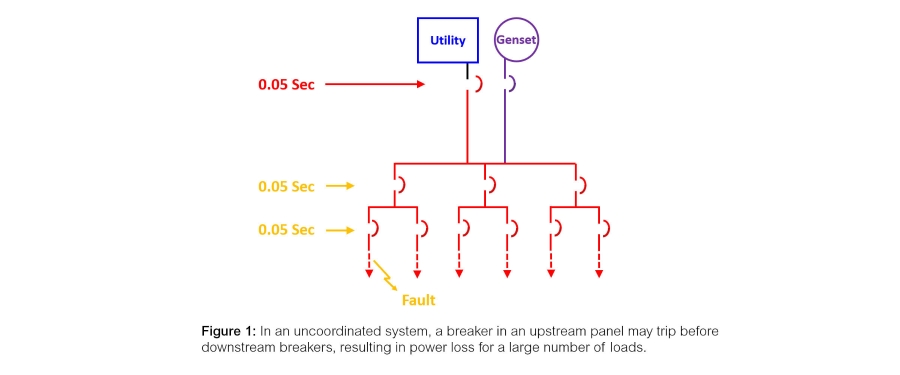
In a power distribution system equipped with multiple levels of overcurrent protection devices, circuit breakers or fuses are located in primary, secondary, and tertiary distribution circuits. If a fault occurs far from the primary distribution panel in an uncoordinated system (a system using devices with similar trip times), it is possible that an overcurrent protection device could open far upstream of the fault location, as shown in Figure 1. The tripped breaker would disconnect power to an unnecessarily large portion of a facility.
SELECTIVE COORDINATION DEFINED

Selective Coordination is an approach where overcurrent protection device opening times are adjusted so that the fuses or breakers located closest to faults open first. Article 100 of the 2020 National Electrical Code® (NEC®) provides a more formal definition:

Localization of an overcurrent condition to restrict outages to the circuit or equipment affected, accomplished by the selection and installation of overcurrent protective devices and their ratings or settings for the full range of available overcurrents, from overload to the available fault current, and for the full range of overcurrent protective device opening times associated with those overcurrents.1

By installing OCP devices with sequential trip times, designers can ensure that the device located nearest to a fault will trip first. This arrangement results in the power interruption to fewer loads and less disruption to the operations served by the power distribution system. Figure 2 shows the local isolation of a fault in a system where opening times have been selectively coordinated across the power distribution system.
DIFFERENCES BETWEEN OVERCURRENT PROTECTION AND TRANSFER SWITCHES

In a fused circuit, a fuse opens when subjected to overcurrent for a prescribed time interval. When a very large overcurrent reaches switched mechanisms such as circuit breakers and ATSs, strong magnetic forces attempt to push their contacts apart, which could open the circuit. To understand the potential impact, it is important to recall the essential purposes of both the overcurrent protection devices and automatic transfer switches.

The primary function of overcurrent protection devices is to disconnect power sources from downstream circuits and loads to avoid unsafe conditions and resulting damage. However, the power switching contacts in a transfer switch must remain closed when overcurrents occur (up to the ratings of the device) until an overcurrent protection device clears the circuit. This allows downstream overcurrent protection devices to work as designed, including any provisions for selective coordination.

NEC PROVISIONS REGARDING SELECTIVE COORDINATION

Selective coordination definitions and requirements are promulgated in the National Electrical Code, which sets forth installation standards for electrical systems and equipment. Specific requirements exist for healthcare facilities, elevator and escalator systems, emergency and life safety systems, and more. Table 1 below lists commonly referenced NEC provisions regarding selective coordination. NFPA 99 – Health Care Facilities Code and NFPA 110 - Standard for Emergency and Standby Power Systems also set forth performance requirements for selectively coordinated systems.
UL 1008 RATINGS

As noted, large fault currents generate magnetic forces that attempt to open switch contacts. If an ATS were to transfer load to an alternate power source during a fault, it must be able to close on and hold that current to avoid power interruption. In addition, large fault currents passing across transfer switching contacts generate heat that can degrade contact materials and surfaces. To become UL 1008 Listed, transfer switches must undergo testing by Underwriters Laboratories or a UL-approved lab to evaluate the amounts of fault current they can withstand and close on for durations specified in the standard or any optional durations specified on the manufacturer’s label. The resulting ratings are known as Withstand and Close-On Ratings, or WCRs.

There is an inverse relationship between the amount of fault current that a transfer switch can handle and the duration it can be held, as shown in Figure 3. Different types of overcurrent protection devices offer differing clearing times. Consequently, an ATS will typically be assigned multiple ratings according to the types of upstream protection that can be used. Example ratings from ASCO transfer switches are shown in Table 2.
Because current-limiting fuses open most quickly and also limit the peak fault current, they provide the highest WCR ratings. Manufacturers also list maximum test values for use with specific circuit breakers. Because these typically open less quickly, the associated values are usually lower than those for fuses.

In addition, manufacturers specify values for coordinating the ATS with circuit breakers other than those on an ATS’ specific list. Because these optional ratings are associated with a 0.025 or 0.05-second test time interval, they are known as Time Based Ratings. Finally, manufacturers have the option of testing switches for longer intervals, and UL 1008 suggests durations of 0.1, 0.13, 0.3, and 0.5 seconds. The resulting values are known as Short Time Ratings. Each type of rating is shown for select ASCO ATSs in Table 2 above.

REQUIRED INFORMATION

Settings for overcurrent protection devices are usually specified following the completion of a coordination study of a proposed power distribution system. Among other parameters, coordination studies evaluate the amount and duration of fault currents at various locations throughout the power distribution system. Engineers then select overcurrent protection settings that will cause downstream breakers to trip before upstream units. As noted, an ATS must hold the anticipated current to prevent inadvertent power outages to loads until protective devices clear the circuit.

To select the most appropriate ATS, the overcurrent protection devices should be known and the results of a completed selective coordination study should be available. At that point, the information needed to select an ATS includes (1) the nominal voltage and amperage of the load, (2) the maximum fault current that will be available, and (3) the duration for which the ATS must hold this current. By comparing this information to transfer switch specifications, an appropriate model can be selected. The WCR Ratings and Short Time Ratings of the ATS must equal or exceed the above-referenced values.

In some applications, specifiers might consider using transfer switches that can hold current for longer durations than required by the coordination study. This practice offers the promise of additional flexibility for selective coordination, particularly when a study is incomplete or plans for further power system improvements are unclear. However, higher-rated ATSs typically weigh more (making installation more labor-intensive and costly), occupy additional space, and have higher purchase costs. In addition, holding circuits closed for a longer duration increases downstream incident energies. This can present additional risk to personnel, and thus affect how equipment can be serviced. Consequently, minimizing opening time differences between overcurrent protection tiers can avoid unnecessary logistics and costs. Figure 4 shows a 30-cycle transfer switch. Coordination schemes with and without 0.5-second switches are compared in Figure 5.
SUMMARY

Selective coordination strategies are used to minimize the number of loads that will be de-energized if a fuse or breaker opens. These strategies enable overcurrent protection devices nearest to faults to trip first, avoiding power disruption to a greater amount of load equipment.

Selective coordination is accomplished by using overcurrent protection devices with longer trip times near the power source and shorter times near load equipment. Automatic transfer switches are not used to selectively coordinate power protection. Instead, they must support selective coordination schemes by closing on and holding greater fault currents than nearby protective devices, and must remain closed until those devices clear the circuit.

Specifying overcurrent protection devices that open later than necessary offers several disadvantages. A resulting selective coordination strategy could require devices, including ATSs, that are larger and more costly. In addition, using long opening times could increase incident energies at downstream locations, which could affect personnel safety and equipment serviceability.

---------------------------------------------------------------------------------------------------------------------------------------------------------
1 National Fire Protection Association. NFPA 70, National Electrical Code®. 2020 Edition. Article 100. p. 70-34.

---------------------------------------------------------------------------------------------------------------------------------------------------------

For further reading:

ASCO Tech Brief:

Three Reasons to Choose UL 1008 Transfer Switches

ASCO White Papers:
UL1008 Transfer Switch Withstand and Closing Ratings
Performance Testing for Transfer Switches
UL 1008, 7th Edition Withstand and Closing Rating Requirements
Selecting IEC 60947-6-1 Transfer Switches for Motor Loads in Mission-Critical Applications

Get the latest white papers, product news and insights straight to your inbox

Subscribe Now