Our Brands

My Documents 0

Welcome to the ASCO Website

Welcome to our website.

Motor Load Transfer Made Simple

A Primer on In-Phase Power Transfer

Switching motor loads between power sources can result in problematic in-rush currents. A prior ASCO White Paper outlined four approaches for mitigating these currents. One approach is to use an in-phase monitor, a solution that ensures transfers occur when phase angle differences will not cause excessive inrush currents. The following sections summarize the operation and application of in-phase monitors in transfer switching.

Defining Phase Angle

Electricity can be produced by rotating a copper coil inside a magnetic field. By powering a device such as an alternator, fuel energy is converted to electricity using a mechanical engine to power rotating equipment.

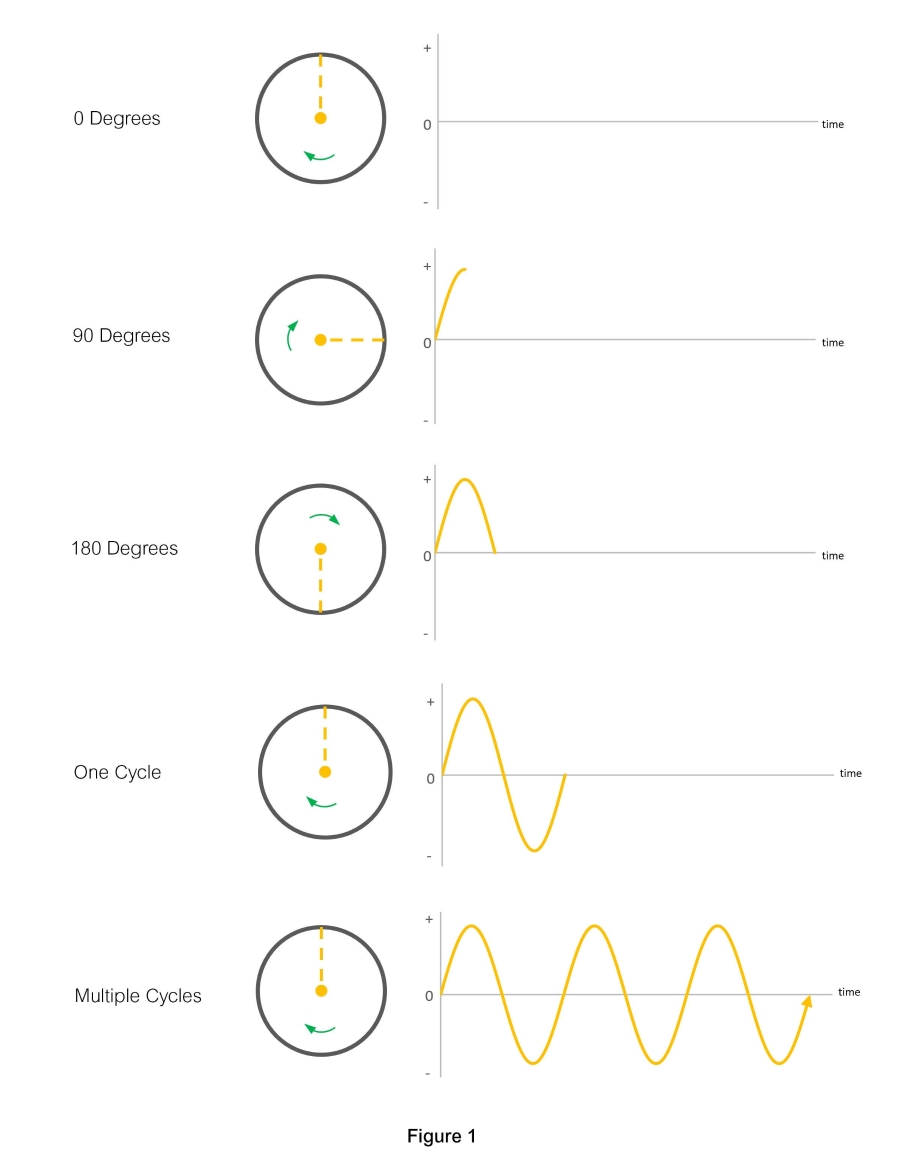
As an alternator’s copper coils rotate within its magnetic field, the polarity of the resulting electrical charge changes twice with each revolution, with the instantaneous voltage increasing and decreasing throughout each cycle. The resulting current alternates in polarity, hence the term alternating current (ac). Figure 1 illustrates the effect of the changing rotational position or phase angle of the generating device, which produces voltage characterized by a voltage sine wave. An ac motor similarly uses a coil inside a magnetic field and rotates with the alternating current it receives.
Limiting In-Rush Currents

Differences in Phase Angle

In an electrical circuit, current flows from a location of high voltage to a location of lower voltage. The rate of current flow is a function, in part, of the difference in voltage between two points along a circuit. When a spinning motor is disconnected from its power source, the motor itself will generate a residual voltage until it slows and stops. When a power source and spinning motor connect, any difference in voltage between them will cause them to instantly attempt to synchronize their rotational positions or phase angles. The devices are considered to be operating in phase when the phase angle differences are negligible.

The issue of inrush currents arises when two out-of-phase devices connect, such as when a running motor is transferred to an alternate power source. Figure 2 shows the sine waves of two out-of-phase devices operating at the same frequency. The amount of inrush current will depend, in part, on the difference in voltage between the two sources at the instant of transfer, as shown at t0 in the diagram.
When the instant voltage difference between the two devices is excessive, large inrush currents could result, which will stress equipment. For comparison, typical motor starting currents can equal approximately six times the normal operating current, but connecting a motor to a power source that is 180 degrees out-of-phase can result in an inrush current equaling 12 to 15 times the normal current. The resulting stress can damage electrical and mechanical components of generators, motors, and other rotating devices. This current can also trip circuit breakers, causing an inadvertent outage to load equipment on an affected circuit.

To avoid large inrush currents, system designers seek to limit the amount of inrush current by limiting the voltage difference when electrical load is transferred to an alternate power source. A common guideline for transferring power between two live sources, such as utility power and a backup generator set, is a maximum phase angle difference of 60 degrees for open transition transfer sequences. At this value, the voltage difference between out-of-phase power sources is similar to the starting current of motors on the circuit.

Differences in Frequency and Voltage

As noted, inrush currents result from the instantaneous voltage differences between sources. Figure 2 above depicts a system where the source and load equipment are out-of-phase but running at the same frequency. In practice, two unconnected or unparalleled devices rarely exhibit the same exact frequency, but passively drift in and out of synchronism at a rate that corresponds to the difference in their frequency and resulting wavelengths, as shown in Figure 3 below. In addition, there are typically voltage differences between the sources, also shown in the figure. To minimize inrush current, transfers should only occur when voltage and frequency differences are within acceptable limits, typically 5% and less than two or three Hertz, respectively.
Adjusting for Elapsed Transfer Time

In a power system operating at 60 Hertz, each ac cycle equals 1/60th of a second or ~16 milliseconds, and the above referenced, 60-degree, phase angle range (1/6th of a cycle) equals ~3 milliseconds. Consequently, when power is transferred between two, live, inductive, ac devices, the switching mechanism must close on its destination source contacts within the 3-millisecond interval, when the potential for inrush current will be lowest.

To ensure this occurs, the switching device must begin to operate early enough to complete its action during the above-referenced interval. In-Phase Monitors thus anticipate the time needed to complete a switching operation with the prescribed contact closure interval. Controllers can use a variety of approaches for doing so, including a fixed advance timing scheme for small differences in frequency or a variable timing window for larger frequency differences.

Provision of In-Phase Monitors

In-Phase Monitors are provided within the electronic controllers of most modern transfer switches. These controllers monitor differences in voltage and frequency between source and load circuits to ensure that power transfers occur when the destination source presents acceptable characteristics. When in-phase monitors are engaged, controllers also track the relative difference in phase angles, then signal a transfer switch mechanism to operate. In doing so, they advance timing to reliably close on the alternate source at the required instant.

Notably, there are situations when in-phase monitoring should not be employed, such as when a connected power source fails. In this scenario, power on that source is decaying and it becomes necessary to transfer power immediately. Because the voltage on that source is decreasing, the potential for inrush currents is also diminishing. To avoid delay, in-phase monitors typically provide a bypass function that engages when source voltage drops below a pre-set level. For example, many ASCO automatic transfer switches use a default in-phase monitor bypass value of 70 percent of the nominal circuit voltage. At this value, the stored energy in a running motor or motors has already dissipated to an acceptable level.

Advantages of In-Phase Transfer

Because in-phase transfer occurs when sources and loads are in or near synchronism (Figure 3), it occurs with minimal impact on power flow, and motors do not need to be depowered before transfer. Because in-phase monitoring works with open transition switching, there may be no need to use a more complex transfer switch or additional devices. Most modern automatic and electrically operated transfer switches provide an in-phase monitor within their controller’s software, so there is no separate control device or control circuit wiring to install. Taken together, these factors can make in-phase transfer the simplest and most cost-effective approach for mitigating inrush currents.

For every motor load application, the need to mitigate in-rush currents should be evaluated in the context of the specific characteristics of motor circuits and the needs of the facility and its end-users. For additional insight, review the documents identified below. For additional information about transfer switching solutions, see the ASCO Transfer Switch Webpage, access the ASCO Digital Binder, or contact an ASCO Power Technologies representative.

--------------------------------------------------------------------------------------------------------------

1 ASCO Power Technologies, Inc. White Paper - Transferring Motor Loads Between Power Sources. 2020. https://download.schneider-electric.com/files?p_enDocType=White+Paper&p_File_Name=asc-ts-wp-119-motorloads.pdf&p_Doc_Ref=asc-ts-wp-119-motorloads. Accessed October 28, 2021.

2 ASCO Power Technologies. Technical Brief – Transition Mode Basics. Undated. https://www.ascopower.com/us/en/resources/technical-briefs/transition-mode-basics.jsp. Accessed October 2, 2021

--------------------------------------------------------------------------------------------------------------

For related reading, see:

• Technical Brief - Basic Automatic Transfer Switch Functions
• Technical Brief - Basic Power Source Synchronization and Paralleling
• Technical Brief - Transition Mode Basics
• White Paper - Transferring Motor Loads Between Power Sources


For additional information, contact ASCO Customer Care.

Get the latest white papers, product news and insights straight to your inbox

Subscribe Now