Connecting power sources when phase angle differences are large can result in strong inrush currents. When inductive loads are present, these currents electrically and mechanically stress equipment and can lead to:
- electrical damage to electrical and electronic components
- mechanical damages to rotating mechanical equipment such as engines, generators, electric motors, and the equipment they power
- nuisance tripping of overcurrent protection devices
For these reasons, phase angle differences must be managed when closing alternate power sources.
Approaches for Managing Phase Angle Differences
When transferring mixed or resistive loads using an open transition transfer switch, phase angle differences may not require further consideration. However, phase angle differences must be managed when significant inductive or motor loads are present. Two approaches are available.
For transfer switching,
In-Phase Monitoring can be used to ensure that connection occurs only when phase angle differences are within acceptable ranges. With in-phase monitoring, transfer switch controllers passively allow power sources to drift towards synchronicity, then initiate transfer so that connection completes when phase angle differences are acceptable. For most load transfer applications, the maximum acceptable difference is 60 degrees.
Source paralleling is conducted by switchgear, and typically involves larger amounts of power. Like in-phase monitoring, switchgear must account for phase angle differences when connecting power sources such as two large generators with high inertial loads. Here, phase angle differences must be more tightly controlled, typically within 5 degrees.
Unlike in-phase monitoring, paralleling solutions actively manipulate engine controls. These may be used to drive power sources to synchronicity and to reduce phase angle differences, and are needed to maintain synchronization until each genset is no longer required
Summary
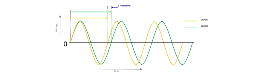
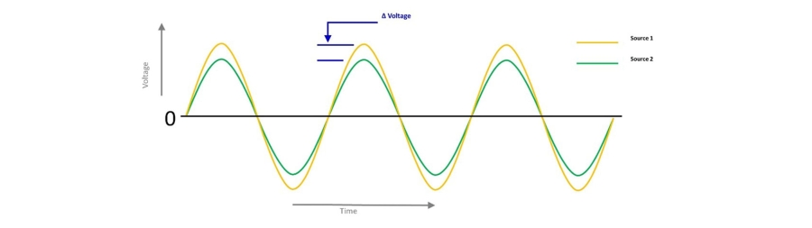
Synchronization focuses on the relative difference in frequency between connectable equipment, and is necessary when transferring loads between power sources. Transfer switches can assure reliable load transfer without excessive transient effects by connecting to alternate power sources only when frequency and voltage differences are acceptable. Where inductive or motor loads are present, in-phase monitoring can be used to close on power sources as they drift into synchronicity. For transfer switching operations, acceptable voltage, frequency, and phase angle differences are typically +/- 5 percent, +/- 0.2 Hertz, and +/- 60 degrees, respectively.
Source paralleling involves larger amounts of power. It requires control of the same parameters as synchronization plus control of phase angle differences. Source paralleling solutions actively adjust engine controls to establish and maintain synchronism and control phase angle differences. For connection, acceptable voltage, frequency, and phase angle differences are typically +/- 5 percent, +/- 0.2 Hertz, and +/- 5 degrees, respectively. Paralleling solutions synchronize power sources until multiple sources are no longer needed.