Our Brands

My Documents 0

Welcome to the ASCO Website

Welcome to our website.

Increasing Power Redundancy

Using Tie Breakers and Segmented Bus

Paralleling Switchgear Systems provide the highest levels of redundancy and maintainability for backup power applications. Understanding the function of tie breakers and electrical bus are key to optimizing backup power system configurations. The following sections describe tie breaker functions and provide examples of bus arrangements for a range of applications.

Overview of Breakers in Electrical Systems

Circuit breakers are used for multiple purposes in electrical systems. They are commonly used to connect electrical systems to power sources and to load circuits, and to protect people and equipment from overcurrents. On the source-side of electrical bus, generator breakers connect generators to electrical distribution bus, and utility main breakers connect electrical power feeds to bus. On the load side, distribution breakers connect and protect downstream loads, either directly or through automatic transfer switches.

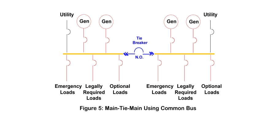
A Tie Breaker is a type of circuit breaker that connects two sections of electrical bus serving different power sources. When closed, current can pass in either direction between them. As a result, they enable various arrangements for connecting power sources to loads, including paralleling two dissimilar power sources. Although this is most often the intent of the term tie breaker, it is also less formally used to identify breakers placed between two sections of bus.

Tie breakers are commonly applied to backup power systems in two ways. A Tie circuit breaker, such as a Utility Bus Tie or a Generator Bus Tie, connects similar power sources. Separately, a Generator Main Breaker ties a generator bus to a load bus. In this location, it can be used to transfer load between a utility source and a generator source. It can also be used to isolate elements of the system to deenergize it for maintenance and repair of devices and their components.

For additional information on the types of breakers used in power systems, see the ASCO Technical Brief entitled Nomenclature for Low-Voltage Circuit Breakers.

Types of Bus

Electrical bus is named for the type of equipment it connects. Common Bus connects both power source and load circuits. Generator Bus connects only generators together, and Utility Bus does the same for two or more utility feeds.

Common Arrangements

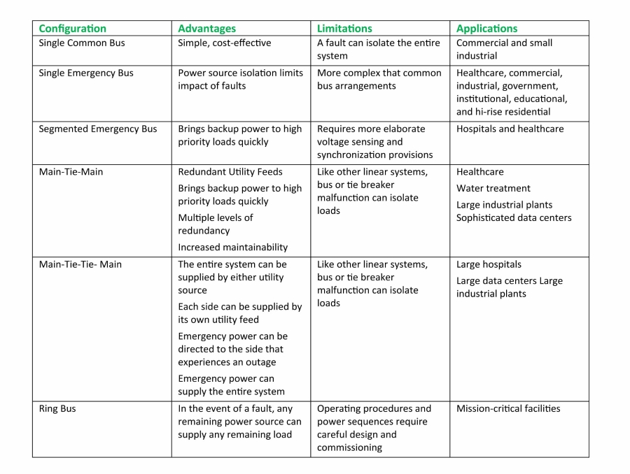
Using tie breakers and bus segments, backup power systems can be configured in a nearly infinite number of ways to meet a wide range of operational and redundancy objectives. The following sections provide samples of the most common types.
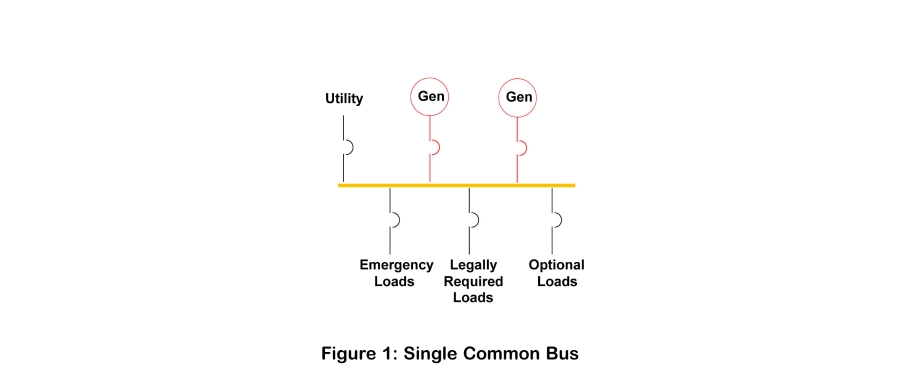
   Single Common Bus

Common bus is the simplest configuration, where power sources and loads are all connected through a single bus. This arrangement is shown in Figure 1. When utility power fails, the utility breaker is opened, then the generators are started and the generator breakers close to provide backup power. Source and load management actions are completed using the circuit breakers shown.
Advantages

Connecting either utility or generator power to the system provides power source redundancy. When each generator is sized to handle the entire load, having an “extra” generator provides a redundant source for backup power so that a generator failure does not impact connected loads. It is easy to design and uses the simplest operation sequences. It is also cost effective.

Limitations

Because all of the sources and loads connect to a common bus, a bus fault can disrupt the function of the entire power system. In addition, the execution of maintenance or repairs can require shutdown of the power sources and/or its associated devices.

Common Applications

Single Common Bus arrangements are often seen in commercial buildings and smaller industrial facilities.

   Single Emergency Bus

Single Emergency Bus connects only generators. Utility power is carried separately to loads, and load control is activated through automatic transfer switches. A dedicated bus or other conductor brings utility power to the transfer switches, which are used to manage load circuits. Figure 2 shows an example.
Advantages

The advantages of this system include those stated for Single Common Bus. However, this arrangement isolates the normal and emergency power supplies from each other. As a result, a fault on the Generator Bus will not disrupt the delivery of utility power to loads, and a fault in the utility power pathway will not affect the availability of the generators.

Limitations

The use of transfer switches and potentially extra circuit breakers increases cost when compared to simpler Common Bus solutions.

Common Applications

Single Generator Bus configurations are deployed over a wide range of applications. They can often be found in the following types of facilities:
  • hospital and healthcare facilities
  • commercial buildings
  • industrial plants
  • government and institutional structures
  • education facilities
  • hi-rise residential buildings
   Segmented Emergency Bus

Introducing a normally open tie breaker allows for use of segmented bus, which is shown in Figure 3. The breaker is used to either connect or isolate the segments according to power source and distribution system conditions. When a utility outage occurs, a transfer switch will signal the generators to start. On each side of the tie breaker, the first generator to produce acceptable power will be connected to its bus, and the highest priority loads will be connected to the bus first. Doing so gets power to emergency loads in the fastest way. Thereafter, additional generators are connected, and additional loads are added according to priority.
Advantages

This arrangement can be used to connect generators to isolated segments to bring multiple gensets online within the 10-second timeframe required for critical power applications. When the tie breaker closes, the generators will share the connected loads equally. This increases overall capacity and maximizes backup power availability if a generator fails. For information on applicable codes, review the ASCO Technical Brief entitled Standards for Backup Power.

The tie breaker also can isolate faults. If one bus is lost, the other keeps the remaining portion of the facility powered. The tie breaker can also be used to isolate one section for maintenance.

Limitations

This arrangement, like the subsequent arrangements that feature tie breakers, requires synchronization across the tie breaker and voltage sensing on each segment. Like gensets, paralleling the respective bus segments requires that voltage, frequency, and phase angle differences be within acceptable ranges at the instant of connection. For more information, review the ASCO Technical Brief entitled Basic Power Source Synchronization and Paralleling.

The Segmented Emergency Bus arrangement requires more complex power event sequences to control the respective devices. System designers must also consider failure modes. For instance, if a tie breaker fails to close, each segment must be independently managed.

Common Applications

The Segmented Emergency Bus arrangement is commonly found in hospitals because it can speed backup power to the highest priority emergency loads in compliance with NEC Article 517 requirements.

   Main-Tie-Main

Main-Tie-Main can refer to several configurations. Historically, it has referred to using two separate utility feeds to provide utility redundancy. The arrangement is simplistically shown in Figure 4.
Adding backup power sources, as shown in Figure 5, continues to offer the redundant capability to connect any remaining power source to any remaining load, provided that no fault occurs at the tie breaker or on either bus.
In common practice, moving the generators to a dedicated bus isolates the two types of power sources as shown in Figure 6. In this arrangement, a fault on one bus will not impact the ability to use the alternate power source.
Advantages and Limitations

Main-Tie-Main systems enable a host of configurations with a variety of potential advantages. These include an ability to run the system using either of the two utility feeds. In Figures 5 and 6, if an outage occurred on both utility feeds, the system could be powered from the gensets, and backup power would reach the highest priority loads quickly.

Additional generator redundancy depends on the size of the gensets. For example, if any three gensets can carry the entire load, the facility could still operate after losing both utility feeds and any single genset, resulting in n+1 generator redundancy. If any two generators can carry the load, 2N generator redundancy is achieved.

With the configuration shown in Figure 5, a tie breaker failure would retain available normal and emergency sources for each side of the electrical system. In Figure 6, the isolated generator and utility systems provide an additional degree of redundancy, where a fault on a utility bus would be isolated from the generator bus, and vice versa. It also offers maintainability advantages – this arrangement enables a facility to isolate one source while maintaining breakers. The facility can also test its backup power system with and without load.

Applications

These configurations can be found in a range of applications, wherever advanced redundancy is required. Nevertheless, the configuration in Figure 5 might be commonly found in water and wastewater treatment facilities, large industrial plants, and sophisticated data centers. A Main-Tie-Main arrangement like the one shown in Figure 6 can be found in large hospitals and healthcare facilities.

   Main-Tie-Gen-Tie-Main

A Main-Tie-Gen-Tie-Main configuration places a dedicated generator bus between two utility busses, as shown in Figure 7. The three busses are connected by tie breakers. The system is normally powered by the separate utility feeds and the tie breakers are open. If one utility feed fails, the system can close the tie breakers to connect power from the remaining utility feed to all loads. If both utility feeds fail, the generators can feed the entire system.
Advantages

Because the utility main breakers and the tie breakers act as transfer pairs, they are electrically interlocked to prevent two power sources from being simultaneously connected to loads. The arrangement provides for a range of strategies:
  • The entire system can be supplied by either utility source
  • Each side can be supplied by its own utility feed
  • Emergency power can be directed to the side that experiences an outage
  • Emergency power can supply the entire system
  • By adding appropriate controls, return to normal power can be executed using closed or soft-load transition sequences that avoid even momentary power interruptions.
Limitations

Because they are electrically interlocked, if a utility main breaker fails to open, loads could be isolated from generators. Because the bus configuration is linear, without further provisions, the loss of any one main or tie breaker will isolate a portion of the loads.

Common Applications

Main-Tie-Gen-Tie-Main configurations are found in large hospitals, large data centers, large industrial facilities, and other applications that rely on more than one utility service.

   Ring Bus

In linear bus configurations, the failure of a tie breaker or a bus can leave loads isolated from a power source. Ring bus configurations place tie breakers between both ends of every bus segment to form a loop. In normal operation on utility power, the tie breakers remain open, and the system operates similarly to linear bus arrangements. If an outage occurs, the breaker positions can be changed to connect any remaining power source to any remaining load, thus providing an additional degree of redundancy. Figure 8 shows a ring bus arrangement.
Advantages

Unlike linear arrangements, ring bus offers two separate pathways between sources and loads on different bus segments. It offers the highest level of redundancy of the examples shown herein.

Limitations

Ring bus are not designed to be run with all tie breakers closed. Such operation could create complex electrical conditions that are beyond the scope of this article. Because this configuration is more complex than a linear design, operating procedures and power sequences require careful design and commissioning.

Common Applications

Ring bus configurations are most often used in large data centers and mission-critical facilities.

Summary

The examples provided underscore the functional value that tie breakers and segmented bus can bring to switchgear systems. In practice, these elements can be configured in a wide variety of ways to optimize redundancy and availability for specific sites and applications. The differences between these systems are summarized in the following table.

Get the latest white papers, product news and insights straight to your inbox

Subscribe Now