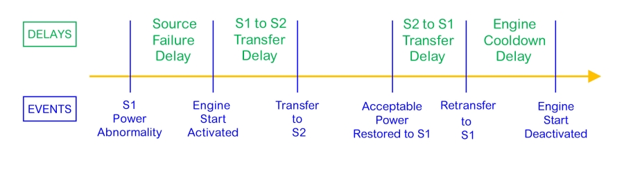
Source Failure Delay
Transfer switches monitor source voltage and frequency, and can detect voltage and frequency aberrations quickly. If a normal source such as a utility service exhibits aberrations for a very short interval, a transfer switch would immediately initiate a load transfer. This action typically involves signaling a genset to start, initiating transfer when it produces acceptable power, then retransferring to the normal source after that source again evidences stability. If the transient condition that triggered the transfer was immaterial to the facility operation, the switching cycle was unnecessary. If open transfer switching is used, the switching cycle unnecessarily introduced two very brief power interruptions. If this occurs often, the cumulative effects of switching activity could be excessively disruptive.
This type of nuisance switching activity can be avoided by delaying the issuance of the engine start signal. Persistence of an unacceptable power condition until the delay interval expires confirms the necessity for transfer and results in issuance of an engine start signal. This delay interval allows overcurrent protection devices to clear faults, if any.
For commercial applications, a typical Source Failure Delay value is 3 seconds. For life safety loads, this delay is often set to zero. The maximum duration of this interval is limited by availability of ride-through power for the controller. For this reason, manufacturers offer transfer switches with a ride-through power capability. The amount of ride-through power capability can vary between models and manufacturers.
Source 1 to Source 2 Transfer Delay
When the Source Failure Delay expires, the ATS controller sends a start signal to the Source 2, then monitors voltage, frequency, and perhaps phase angle to determine acceptability of Source 2 power. However, prime movers may require a short time interval to stabilize so that they can reliably accept the emergency load, especially where internal combustion gas engines are coming online from a cold start. Invoking a S1 to S2 Transfer Delay allows the genset to stabilize. The load transfer sequence is initiated when the S1 to S2 Transfer Delay expires.
S1 to S2 Transfer Delay values are set according to the needs of the facility and application. Where facilities can tolerate short outages, this delay may be set to 30 seconds or more. Where operations require power quickly, a delay of 5 seconds might be set. Again, for life safety loads, a zero value may be used.
S1 to S2 Delays are especially useful where power is distributed through more than one transfer switch. Delays can be staggered across switches to avoid block loading, where the entire emergency load is placed on the alternate power source in a single instant. Instead, the S1 to S2 Delay for each transfer switch can be staggered according to their priorities. For instance, if ATS 1, ATS 2, and ATS 3 respectively serve life safety, critical, and optional loads, then sequential delays could be used to assure smooth transfer without excessive block loading and potential momentary generator overload.
Source 2 to Source 1 Transfer Delay
Transfer switches return to the normal source after (1) acceptable power has been restored to Source 1, or (2) testing of Source 2 is complete. As before, it is best practice to ensure that Source 1 is stable before load is connected to it. Introducing delays again enables sequential retransfer of multiple transfer switches. When the delay(s) expires, the retransfer sequence(s) is executed. Some manufacturers offer secondary delays that optimize operation according to the nature of the event that triggers the initial transfer.
Engine Cooldown Delay
After power is restored from Source 1 and retransfer is complete, power from Source 2 is no longer needed. However, before shutting down Source 2, a cool-down period without load is typically required, especially when units have been operated at high load. Cooldown duration should follow genset manufacturer recommendations. Typical durations range from 10 to 30 minutes. Again, manufacturers may offer secondary delays for optimizing cooldown operation under specific circumstances.
Because excessive low-load operation can lead to conditions that decrease equipment reliability and longevity, the cooldown delay should not be set longer than necessary. For more information, read ASCO Power Technologies’ white paper entitled Manage Load To Avoid Diesel Wet Stacking.
Summary
ATS timing delays are used to avoid unnecessary transfer and to optimize equipment operation. Delays involved in a basic transfer switching cycle include
Source Failure Delay, Source 1 to Source 2 Transfer Delay, Source 2 to Source 1 Transfer Delay, and Engine Cooldown Delay. The use and duration of these delays should always be evaluated in the context of site-specific operations and the associated priorities for different types of load.
Where more than one transfer switch is served by a power source, delays provide operational flexibility and can be used to avoid excessive block loading. Users should ensure that delay settings conform to any applicable codes and regulations. Further support for evaluating delay settings and learning about more advanced timing delay applications generally can be obtained from switchgear and genset manufacturers, and specifically by contacting an
ASCO Power Technologies representative.