The most common applications for transfer switches include power distribution circuits that serve a mix of load types, including resistive loads for building lighting and heating as well as inductive loads such as motor-driven equipment. However, some transfer switches may supply a circuit that includes one or more large motors or may feed multiple circuits that serve primarily motor loads. Examples include air handlers in large commercial buildings, air conditioning compressors for data center cooling, or the many water pumps required to operate a wastewater treatment facility.
Where backup power systems supply circuits that primarily serve motor loads, consideration must be given to in-rush currents that result when motors are out-of-phase with the alternate power source. This document summarizes approaches for avoiding excessive in-rush currents that could trip breakers, damage motors and load equipment, and overload generators when transferring motor loads.
AVOIDING DAMAGE TO MOTORS
When an outage occurs on a primary power source, voltage on that source is decaying or absent. However, when loads are returned to the Normal source and when backup power systems are subject to routine testing, they are transferred between two sources that are both at full voltage. If completed without appropriate controls, transfer where motors and the alternate source are significantly out-of-phase can result in abnormal in-rush currents that can trip overcurrent protection devices and damage motor windings, insulation, couplings, and perhaps load equipment. Four provisions for mitigating these effects include:
•In-phase transfer
•Motor load disconnect circuits
•Delayed transition transfer switching
•Closed transition transfer switching
In-Phase Transfer
When switching between sources, automatic transfer switches (ATSs) monitor the voltage and frequency of the sources, then close on the alternate source only when these parameters are within acceptable limits. When motor loads are involved, in-phase monitoring can also be used to reduce in-rush currents, as follows.
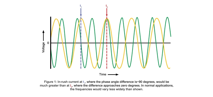
Figure 1 shows sine waves representing phase voltages for two different power sources. Because their frequencies differ, they pass in and out of unity. If load is transferred when the voltages are dissimilar, current immediately flows from highest to lowest potential until the resulting forces cause the rotating generator and motor to synchronize. If this occurs when the phase angles vary widely, such as at t1 in Figure 1, then the in-rush currents will be larger than if they occur near unity, such as at t2.
Where backup power systems supply circuits that primarily serve motor loads, consideration must be given to in-rush currents that result when motors are out-of-phase with the alternate power source. This document summarizes approaches for avoiding excessive in-rush currents that could trip breakers, damage motors and load equipment, and overload generators when transferring motor loads.
AVOIDING DAMAGE TO MOTORS
When an outage occurs on a primary power source, voltage on that source is decaying or absent. However, when loads are returned to the Normal source and when backup power systems are subject to routine testing, they are transferred between two sources that are both at full voltage. If completed without appropriate controls, transfer where motors and the alternate source are significantly out-of-phase can result in abnormal in-rush currents that can trip overcurrent protection devices and damage motor windings, insulation, couplings, and perhaps load equipment. Four provisions for mitigating these effects include:
•In-phase transfer
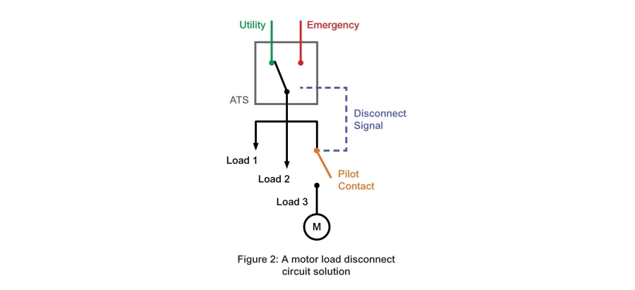
•Motor load disconnect circuits
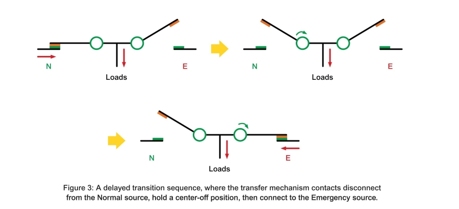
•Delayed transition transfer switching
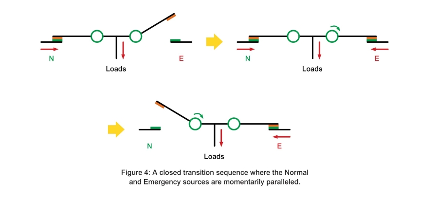
•Closed transition transfer switching
In-Phase Transfer
When switching between sources, automatic transfer switches (ATSs) monitor the voltage and frequency of the sources, then close on the alternate source only when these parameters are within acceptable limits. When motor loads are involved, in-phase monitoring can also be used to reduce in-rush currents, as follows.
Figure 1 shows sine waves representing phase voltages for two different power sources. Because their frequencies differ, they pass in and out of unity. If load is transferred when the voltages are dissimilar, current immediately flows from highest to lowest potential until the resulting forces cause the rotating generator and motor to synchronize. If this occurs when the phase angles vary widely, such as at t1 in Figure 1, then the in-rush currents will be larger than if they occur near unity, such as at t2.