Automatic transfer switches can employ a range of sequences for transferring electrical load between two power sources. Consequently, it is important to understand their differences. This brief explains three of the most commonly available load transfer sequences and their applications.
Background Information
Automatic transfer switches monitor voltage and frequency on the normal power source, typically an electrical utility service. When unacceptable voltage or frequency is sensed, the transfer switch initiates a series of events that include transferring the electrical load to an emergency power source, then retransferring load back to the normal source when power is restored. For a primer on basic transfer switch operations, review the ASCO Power Technologies briefs entitled Basic Automatic Transfer Switch Functions.
Several transfer sequences can be used to transfer loads. The three most common are open transition, delayed transition, and closed transition.
Open Transition Load Transfer
The simplest mode for transferring load between two power sources is the Open Transition sequence. The associated sequence of operation for the switching contacts can be informally described as “break-before-make”. This sequence results in a very brief interruption of power in the range of multiple tens of milliseconds, a value that can vary according to switch mechanism design.
Figure 1 shows a conceptual diagram of a transfer switch contact positions during a retransfer from an emergency power source to a normal power source using an open transition sequence. Figure 2 plots the switch’s corresponding output voltage during the transfer, where V is voltage and t is time.
Transition Mode Basics
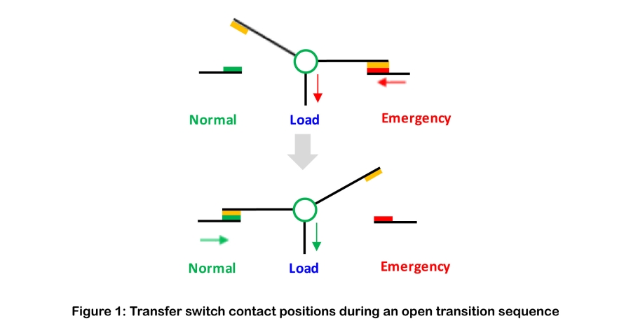
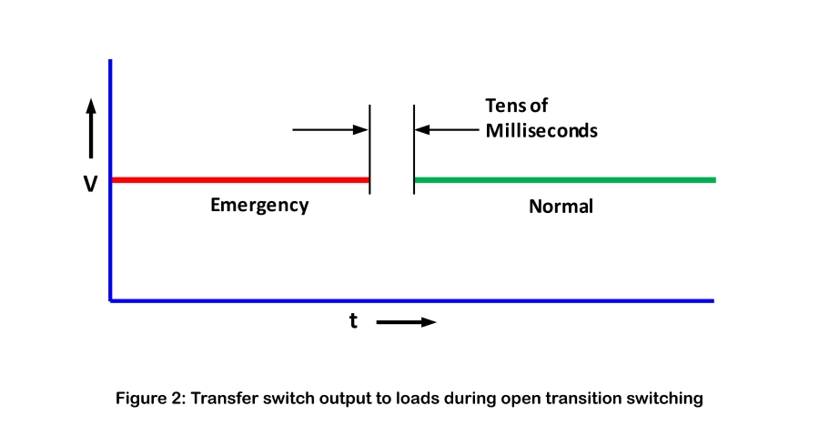
Open transition transfer switching is suitable for a wide range of applications and is used across a wide range of facilities. It provides reliable service in facilities with resistive loads or mixture of resistive and inductive loads. For applications where phase angle differences between sources must be in acceptable ranges, open transition switches can be provisioned with phase angle monitors that ensure proper transfer. For more information regarding the role of frequency, voltage, and phase angle differences in transfer switching, refer to the ASCO Technical Brief entitled Basic Power Source Synchronization and Paralleling.
Delayed Transition Load Transfer
When powering circuits that supply motors, transformers, or other inductive loads, transfer switching should be controlled in ways that limit the possibility of large inrush currents, which can potentially disrupt operations and damage load equipment. By introducing a delay in the transfer sequence, energy in inductive loads can be allowed to day to manageable or nonexistent levels before connecting an alternate power source.
One way to do this is to use a switching mechanism with dual operators. This arrangement facilitates the stepwise operation of the transfer mechanism contacts. Typically, the duration of the delay can be adjusted for the particular application. Figures 3 and 4 show the contact positions and switch output through a delayed transition sequence.
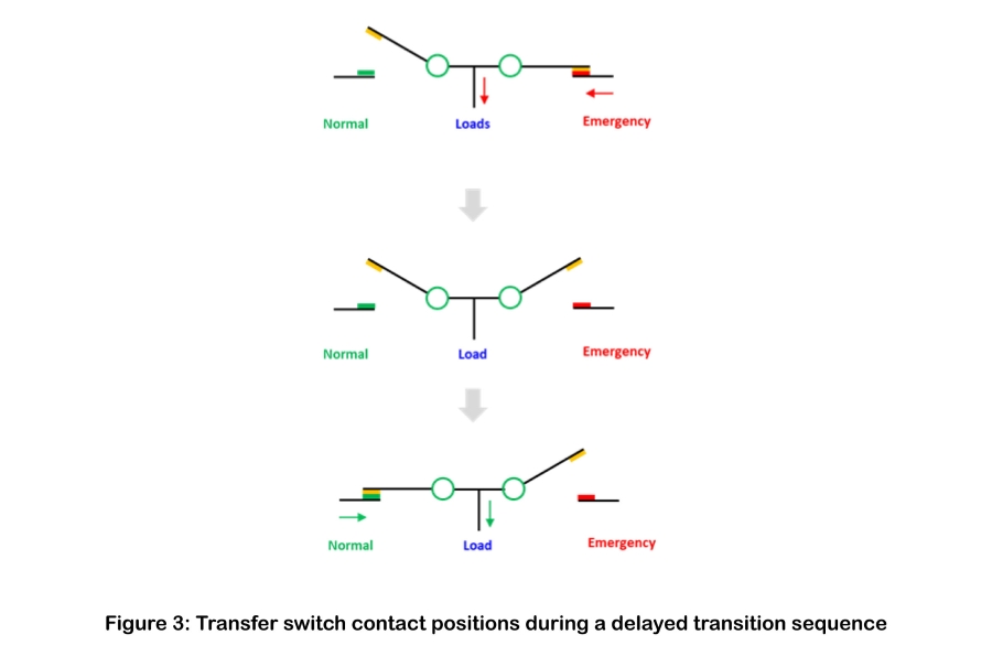
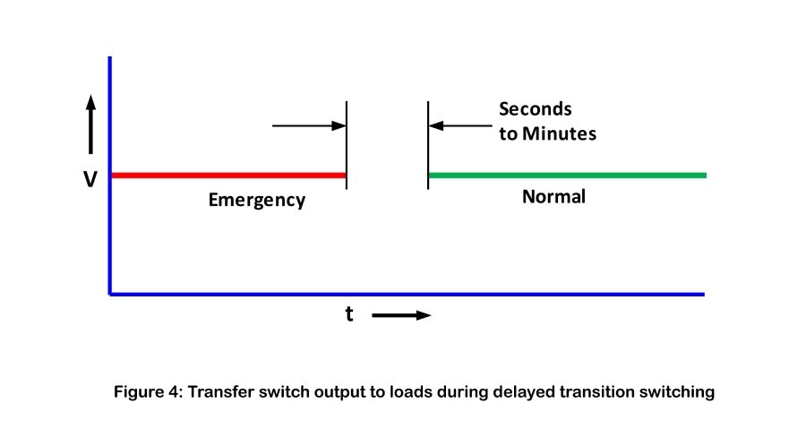
Delayed transition is one of several approaches that can be used to manage transfer of motor and inductive loads. For more information, review the ASCO document entitled Transferring Motor Loads Between Power Sources.
Closed Transition Load Transfer
Many facilities cannot tolerate even very brief interruptions in power flow. Common reasons can include (1) the sensitivity of valuable downstream equipment to power fluctuations and (2) a desire to minimize even the smallest power disturbances because of the mission-critical function of the load equipment and facility. A closed transition transfer switch meets these needs by providing continuous power when switching between two live power sources.
Closed transition sequences momentarily parallel two power sources. Referred to as make-before-break switching, it is accomplished by closing on the contacts of the alternate power source prior to disconnecting from the active source. The sequence is shown in Figure 5 and the output of the transfer switch during the sequence is shown in Figure 6.

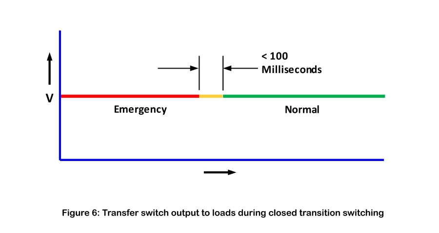
Paralleling of power sources during transfer must be very brief to avoid technical difficulties. For this reason, closed transition transfer switches are provisioned with features to avoid extended paralleling, In addition, utility power providers typically maintain standards for applying closed transition transfer sequences, and switch installation may require direct coordination with utility officials. For more information, review the ASCO document entitled Connecting Closed Transition Transfer Switches to Utility Services.
Summary
Understanding transition sequences is essential to understanding and selecting automatic transfer switches. The three most common are open transition, delayed transition, and closed transition. Open transition transfer switches serve a broad range of applications where resistive or mixed loads are present. Delayed transition transfer switches extend the Interruption of power to allow inductive and motor loads to decay, thereby mitigating damaging inrush currents that might otherwise occur. Closed transition transfer switches close on the alternate source before opening on the initial source to prevent interrupting power flow to sensitive or mission-critical equipment. Deployment of closed transition transfer switches can require close coordination with any utility power provider.