Three types of transfer switches are available for transfer electrical loads between power sources. Automatic Transfer Switches (ATSs) monitor power conditions and transfer between sources, as needed, without human intervention. Non-automatic Transfer Switches (NTSs) transfer loads to an alternate source when prompted by an operator through electrical controls. Manual Transfer Switches (MTSs) require someone to manually transfer loads using external operating handles on the equipment. This paper describes the features associated with each type and the applications for which they are best suited.
Typical Transfer Switch Applications
Of the three types of transfer switches, ATSs offer the most sophisticated feature set. These switches monitor the Normal power source to detect power disturbances, transfer loads to an Emergency source when necessary, and then retransfer loads when the Normal power source is restored, all without operator intervention.
Fully automatic transfer switches may be unnecessary in applications where personnel are present and loads do not require immediate, automatic power restoration. Industrial facilities, water and wastewater treatment plants, farms, and residences are typical applications where a simpler and less expensive NTS or MTS may be used. In applications where backup power must be available even when servicing a facility’s sole generator, Article 700.3(F) of the National Electrical Code® requires that a permanent switching means be provided to connect an interim source of secondary power (Figure 1). For facilities without a permanent backup generator, an MTS and a connecting means can facilitate the connection of a temporary or portable generator when needed, without the cost of a permanent engine-generator.
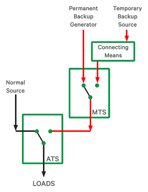 Figure 1: An MTS and a Connecting Means Satisfies NEC Article 700.3(F).
A typical manual or non-automatic transfer switch might be installed at an industrial plant. In this application, a power interruption would not be injurious to human life. However, an NTS or MTS could enable the provision of backup power to maintain one or more of the facility’s industrial processes during an outage of the normal power source, and thus avoid costly downtime. Other applications include cellular telecommunications facilities, a gasoline station, or a small business. In each instance, short power interruptions may be tolerable, allowing for the use of a low-cost backup power solution that utilizes an NTS or MTS.
Locations with Limited Access
Electrically operated NTSs are sometimes selected because they offer convenience of use. These switches can also be equipped with remote controls, such as a remote annunciator/controller, multi-device touchscreen annunciator, or a web-based monitoring and control system (Figure 2). The remote control panel can be located in a distant room with other building management system controls. The newest remote annunciators can be used to control switch functions through a touchscreen interface. Auxiliary contacts on the transfer switch can be connected to a remote annunciator to indicate the position of the switch and confirm whether it has transferred loads to the alternate source.
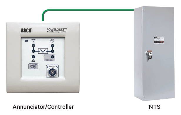 Figure 2: Electrically operated NTSs with remote controls can be operated from a distant location using a remote control panel or a touchscreen annunciator.
Motor Transfer
When transferring motor loads, it is important to account for the potential effects of high inrush currents. These effects occur due to residual energy that is present when motors are disconnected from a power source, especially when transferring to an out-of-phase source. The potential impacts can be mitigated by (1) using in-phase motoring to transfer when sources are synchronized, (2) using delayed transition transfer switch, or (3) using an MTS equipped with a 3-position center-off switch. In the latter application, motors will have adequate time to slow while the switch is in the center-off position. Consequently, training an operator to pause in the center off-position for an appropriate amount of time is the simplest solution for managing motor-related in-rush currents.
Design Considerations
Double-throw knife switches and safety switches have occasionally been used for manual load transfer applications. However, many of these devices must be operated only under “no-load” conditions, where the operator must open breakers or other load-interrupting devices to ensure that the load has been disconnected before it is transferred. These types of devices are often restricted in their application because they are tested to UL 98 - Standard for Enclosed Switches, and not to UL 1008 - Standard for Transfer Switches. As a result, they may not be suited for all classes of load. More importantly, without UL 1008 test data, the ability to transfer between two “hot” unsynchronized power sources cannot be verified. Furthermore, UL 98-listed switches do not carry short-circuit withstand and closing ratings for use with separate overcurrent protective devices. Because the UL 1008 test requirements are more stringent, owners can be confident that the switch will reliably transfer loads for years to come.
For maximum reliability and operator safety, system designers should specify NTSs and MTSs that have the same load-handling characteristics as automatic transfer switches. A minimum level of capability can be assured if the specifier requires conformance to UL 1008. A switch listed to this standard facilitates compliance so that an electrical inspector, who is primarily concerned about electrical safety and fire hazards, can approve an installation. The following table compares important UL 98 and UL l008 test requirements.
| UL 98 and UL 1008 Test Requirements Compared |
| UL 1008 |
UL 98 |
| Overload |
| Tested with total systems load including 100% motor loads. Tested at 600% of rated current at 0.4 to 0.5 power factor for 50 cycles of operation.
|
Tested at the unit’s General Purpose rating. Tested at 150% of rated current at 0.75 to 0.8 power factor for 50 cycles of operation.
|
| Contact Opening Test |
| Tested at 10 times the rated current. The test circuit power factor shall be 0.4 to 0.5 for currents of 10,000A or less, 0.25 to 0.3 for currents of more than 10,000A to 20,000A, and 0.2 or less for currents greater than 20,000A.
|
Test current is 600% at 0.45 to 0.5 power factor. Three test cycles for polyphase circuits and 5 for single-phase circuits.
|
| Endurance |
| Tested for use with total system loads where one-half of the test cycles are at 200% of the rated current and the remainder is at 100%.
|
Making and breaking 100% of rated current with a power factor of 0.75 to 0.8.
|
| Tested with and without current for prescribed quantities of cycles. Quantity of cycles with current is higher than UL 98 for most amperages. See UL 1008 for specific requirements.
|
Tested with and without current for prescribed quantities of cycles. Quantity of cycles with current is lower than UL 1008 for most amperages. See UL 98 for specific requirements.
|
| Temperature |
| Conducted on sample previously subject to overload testing.
|
Conducted on a new, unused test sample.
|
| Short-Circuit Withstand Current |
| UL tests are required. Minimum test rating depends on switch rating as follows: (1) Up to 100A: 5,000A; (2) 101A to 400A: 10,000A; (3) Above 400A: 10 times rating but not less than 10,000A. Both short-circuit withstand and circuit-closing tests must be run on the same sample without the benefit of the maintenance.
|
Required for switches (1) marked for use with overcurrent protection devices having a continuous current rating exceeding that of the switch and short circuit ratings exceeding 10,000A, or (2) unfused switches having 5,000A, 7,500A, or 10,000A ratings. The circuit-closing test may use a new, previously untested sample.
|
|
Feature Comparison
The following sections describe common features of non-automatic and manual transfer switches.
Electrically Operated
Electrically operated switches can be configured to use a local and/or remote control panel. Operation from one or more locations is simple and convenient, especially when transfer switches are placed in locations where there is limited space for user access.
Electrically operated switches can be converted to automatic operation at any time. For example, a portable generator with a pushbutton manual switch can be changed to a permanent on-site generator set with automatic operation. Standard size automatic transfer switch enclosures are normally used so that the existing controls can be replaced by a standard automatic control panel without modification. A new interconnecting wiring harness would typically be furnished with the automatic control panel.
Manually Operated
A manual transfer switch operates similarly to the electrically operated type, except that mechanisms are activated by a person operating a handle located on the exterior of the enclosure. The main operating springs are preloaded to present break, make, and current-carrying capabilities that are identical to electrically operated switches. For maximum safety, handles should conform to UL I008 requirements for manual operation. These handles should also be operable without opening the enclosure. Manually operated units are suitable for installations where the transfer switch is easily accessed, remote control is unnecessary, and in-phase transfer of motors loads and load-shed are not required.
Manual transfer switches are available in a 2-position configuration that transfer loads directly between two sources, and in a 3-position design that adds an OFF position between the two load positions. One advantage of 3-position switch is that moving through the OFF position allows motors to slow before transferring load to the alternate power source, thus avoiding excessive inrush currents. These switches also allow users to pad-lock the handle in the OFF position for safety or maintenance purposes. A 3-position switch is shown in Figure 3.
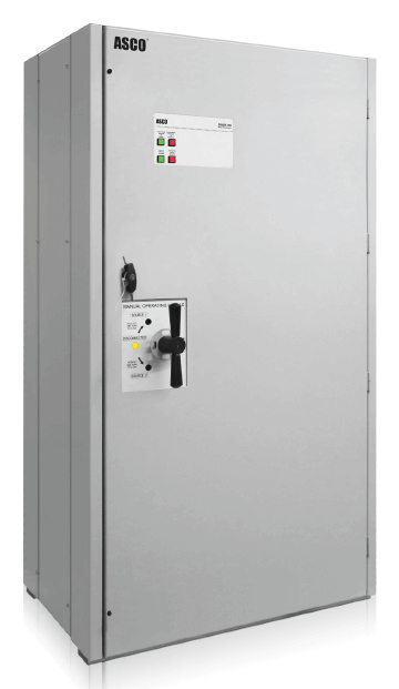 Figure 3: Three-position switches allow motors to slow before loads are transferred to an alternate power source. This helps avoid excessive inrush currents.
Operating Non-Automatic and Manual Transfer Switches
Non-automatic and manual transfer switches differ in operation from automatic transfer switches because the user must determine when conditions are acceptable for transferring loads. It is essential that these switches are operated only by personnel who are properly qualified, trained, and authorized. The operator must determine that the characteristics of the alternate power source are acceptable before transferring the load. The alternate source must not only evidence sufficient capacity, but also proper voltage and frequency.
Inadvertent operation or uninformed operators can create serious situations, such as overloading the alternate source, which could cause an outage of the backup power system. Connecting the load to a source with inadequate voltage may also impair operation of the connected equipment. Consequently, manual transfer switches should be operated by personnel who understand the design and operation of a facility’s engine-generator, its transfer switches, and the distribution systems that they serve.
References
National Fire Protection Association, NFPA 70 - National Electrical Code, Fourteenth Edition, 2017. Quincy, Massachusetts, 2016.
National Fire Protection Association, NFPA 99 - Health Care Facilities Code – 2015 Edition. Quincy, Massachusetts, 2015.
National Fire Protection Association, NFPA 110 - Standard for Emergency and Standby Power Systems - 2016 Edition. Quincy, Massachusetts, 2015.
Underwriter Laboratories, UL 98 - Enclosed and Dead-Front Switches, 13th Edition. Northbrook, IL. 2004.
Underwriter Laboratories, UL 1008 - Enclosed and Dead-Front Switches, 8th Edition. Northbrook, IL. 2014.