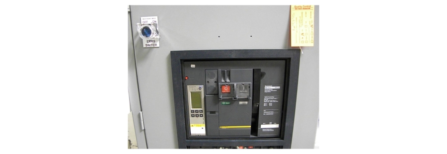
In the 2017 National Electrical Code® (NEC®), Article 240.87 – Arc Energy Reduction requires that a method for reducing fault clearing time be provided when equipment is supplied with electricity through overcurrent protection devices rated (or adjustable to) 1200 Amps or higher. To reduce available arc energy, many electrical equipment manufacturers offer Energy- Reducing Maintenance Switches (ERMS), which is one of the NEC-approved methods, for use with their equipment. The following narrative describes the approved methods and explains ERMS design and use.
BACKGROUND INFORMATION
Electrical equipment service activities present arc flash risks to workers, which employers must manage in accordance with government regulations and industry codes. Arc flashes result from arcing faults, which occur when dielectric breakdown forms a low-resistance path through substances between two electrical conductors, allowing current to pass through air. When such faults occur, they release energy in the form of heat and pressure, which can injure people and cause property damage. In addition, arc flashes emit radiation and debris that can damage eyes and burn skin. Because arc faults can occur at relatively low current levels, they may not trip overcurrent protection devices.
Government regulations and industry standards address methods for mitigating arc fault risks. In 1970, the United States Congress enacted the Occupational Health and Safety Act. This statute requires that employers provide workplaces that are free of recognized hazards, including electrical hazards. The Act also created the Occupational Health and Safety Administrations (OSHA), which issues workplace safety regulations and enforces their implementation. Electrical safety regulations are found in the US Code of Federal Regulations, including 29 CFR 1910 and 29 CFR 1926, which address safety in workplaces and construction sites.
To assist OSHA in regulating electrical safety, the National Fire Protection Association developed NFPA 70E: Standard for Electrical Safety in the Workplace. Compliance requires that a hazard assessment be conducted for arc flash risks at electrical equipment located throughout workplaces. Both NFPA 70E and IEEE 1584-2002 - Guide for Performing Arc Flash Hazard Calculations provide methods for performing the necessary assessments. Addition detail can be found in our prior white paper entitled Arc Flash Studies and Transfer Switch Serviceability.
OPTIONS FOR REDUCING ARC ENERGY
Equipment installation practices are specified by the NEC. When overcurrent protection devices are rated or adjustable to 1200 Amps or more, NEC Article 240.87 requires that a method for reducing available arc energy be provided. The standard provides the following options:
1. Zone-selective interlocking
2. Differential relaying
3. Energy-reducing maintenance switching with local status indicator
4. Energy-reducing active arc flash mitigation system
5. An instantaneous trip setting that is less than the available arcing current
6. An instantaneous override that is less than the available arcing current
7. An approved equivalent means
Notably, the NEC does not state a performance or testing requirement for the listed methods. Each option is summarized as follows.
Zone-Selective Interlocking
Understanding Zone-Selective Interlocking (ZSI) also requires an understanding of selective coordination of overcurrent protection devices in electrical power distribution systems. In selectively coordinated systems, upstream circuit breakers use longer preset trip intervals and downstream units are set to trip more quickly. This arrangement causes the breaker located closest to the fault to open, thus minimizing the amount of equipment that is depowered. Figures 1A and 1B compare an uncoordinated system to a selectively coordinated system. For additional information, review our white paper entitled Selective Coordination Basics.