Our Brands

My Documents 0

Welcome to the ASCO Website

Welcome to our website.

Performance Testing for Transfer Switches

Industry standards specify performance tests that must be completed to verify the safety and functionality of transfer switches. Learning about observed effects of repetitive tests can underscore the value of installing thoroughly tested equipment in end-use facilities. This paper summarizes the need for, nature of, and effects seen during switching tests, and discusses how the results benefit end users.

POSSIBLE TRANSFER SWITCH FAILURE MODES

In order to understand the need for transfer switch switching tests, it is best to review some of the possible ways that inadequately tested or mis-used transfer switches could fail. Three potential problems could include (1) degradation of transfer mechanism performance, (2) degradation of contact materials, and (3) inability to extinguish the arc produced by contact during switching.

Degradation of Transfer Mechanism Performance

Transfer switch mechanism operation can degrade in ways that cause performance or reliability issues. The most profound mode is if a switch mechanism were to seize, preventing operation; or, more likely, be bound or restricted in some fashion that causes it to move less freely. Causes could include improper design or a manufacturing defect. Thorough mechanical testing is necessary to verify that a switch can repeatedly and reliably operate when subjected to foreseeable stresses. UL 1008 specifies testing transfer switches under severe conditions for extensive cycles to assure that designs are safe and adequate.1

Degradation of Contacts

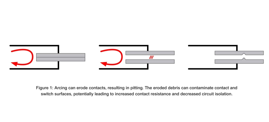
Contacts in a transfer switch mechanism are composed of alloys of metallic and refractory materials. When repeatedly opened and closed, arcing erodes the contact surfaces, which increase electrical resistance across the contacts (Figure 1). Contact erosion also reduces the contact force as a function of reduced spring deflection.
Under normal operation, transfer mechanism contacts generate heat that is proportional to electrical resistance across the contact surfaces. When contact wear is excessive, resistance may increase to a level that raises temperatures in materials of surrounding objects and components. When the temperatures of structural and insulating components rise, these materials could soften and deform. In turn, these conditions could lead to failures that effect the safe and proper operation of a switch. In addition, elevated temperatures may reduce insulating properties of materials, in turn reducing circuit insulation and increasing the possibility of shunts or shorts that could compromise switch reliability and safety.

Failure to Extinguish Arc During Transfer

To maintain safety, reliability, and power quality, isolation must be maintained between opposing power source circuits to avoid shorts.

When a transfer mechanism opens its contacts, arcing occurs between their surfaces. As the load is transferred between live power sources, the opening of the contacts draws this arc across open air. To extinguish this arc, the mechanism is equipped with an arc chute fitted with metallic splitter plates that lie along the contact path of travel.

If the transfer mechanism or the arc chute components do not function as intended, performance issues can result. For instance, if the mechanism moves too fast, it may draw arcs onto opposite source contacts, leading to a source-to-source short. To maintain circuit isolation during transfer, the transfer mechanism must extinguish the arc under all conditions and current levels when energized contacts are opened.

OVERVIEW OF RESPONDING TESTS

UL 1008 specifies a suite of tests to verify that transfer switch safety and performance. These tests are performed on enclosed samples in the following order2,3:

1. Normal Operation
2. Overvoltage
3. Overload
4. Endurance
5. Temperature Rise
6. Short Circuit
7. Dielectric Withstand

The temperature test can be performed after the Endurance Test, or on a separate sample that has been subject to an overload test.

Tests with the most profound implications for switch safety and longevity include Overload, Endurance, and Temperature Rise, and are the primary subjects of this document. Withstand and Closing Ratings for transfer switches are derived from Short Circuit Testing, which is summarized in ASCO’s White Paper 110 – UL 1008 Transfer Switch Withstand and Closing Ratings.4 The results are used to assess whether stresses from foreseeable currents lead to unsafe conditions.

Overload Test

An overload test of a transfer switch requires cycling electrical load between power sources while the switch carries a prescribed overcurrent. UL 1008 codifies test parameters according to switch ampacity. These values are summarized in Tables 1 and 2 below. The minimum contact time in each switch position is 0.167 second, equaling 10 cycles in a 60 Hertz ac system.
The values in the tables define the parameters of the load test. For instance, to verify the performance of a nominally rated 800 Amp ac transfer switch serving Total System Loads, it must be subject to 4800 Amps at a power factor between 0.4 and 0.5 for 50 cycles at four cycles per minute.

Temperature Rise

The Temperature Rise Test is typically performed following the Overload Test. Coils and heating elements in the switch are energized while the sample transfer switch carries 100 percent of rated load continuously. Thermocouples and a measuring device are used to record temperatures of key components, while resistance measurements may be used to evaluate temperatures of coil windings. The test is run until temperatures equilibrate over time.

Article 9.8.1 of UL 1008 specifies that “transfer switches shall not attain a temperature at any point high enough to constitute a risk of fire or to damage any materials employed in the device ...” The standard also specifies that temperatures of specific components should not exceed those identified in Table 3.
Endurance Test

Electrical and mechanical endurance tests are performed using the parameters listed in Tables 4 and 5 below. Depending on switch ampacity, addition cycling without current may be needed. The tests are run under the conditions of the Overload Test, but with different values for test current, quantity of operations, and cycling rate, which are presented in the table.
UL 1008 specifies an important additional condition regarding the quantities of endurance test cycles. For switches rated for total system, motor, or electric discharge lamp loads, half of the cycles with current must be completed using 200 percent of rated load, while the remaining cycles are tested at 100 percent of rated load. This means the most robust transfer switches should carry a manufacturer’s label indicating it is suitable for “Total System Loads”.

UL 1008 offers the option of performing fewer cycles when endurance testing switches that will be listed only for use in optional standby power systems, and not emergency and legally required systems. Under this provision, all tests are performed using the switch’s rated current. The corresponding parameters are presented in Table 5. As a result, not all transfer switches may be rated for use with all types of loads. For this reason, it is important to check manufacturer ratings.
Dielectric Voltage Withstand Test

One reason to perform dielectric withstand testing is to evaluate the effect of contamination produced by operations of the transfer mechanism. As the transfer mechanism is cycled, arcing activity and mechanical action result in degradation and wear of the mating contact surfaces. This produces particulate contamination that typically contains electrically conductive carbon and metallic particles. Deposits of these materials can allow current to leak between normally isolated circuits. This is why cleaning is included in periodic switch maintenance procedures.

Following Overload and Endurance Tests, a Dielectric Voltage Withstand Test is performed to verify that power sources remain electrically isolated. This is performed by placing 1000 Vac plus twice the switch’s rated voltage onto key contacts and terminals for at least one minute. These measurements are recorded across six sets of locations within the transfer switch.

PASSING CRITERIA

Passing an Overload Test depends on the results of a subsequent Temperature Rise Test. Temperature differences that remain within the prescribed limits show that test activities have not degraded switch contacts sufficiently to cause resistance heating that would overheat the switch. It also indicates that the temperatures did not reach levels that would cause structural and insulating materials to soften, which could result in (1) component deformation that could affect switch operability, performance, and safety; or (2) loss of insulating properties that could otherwise increase the opportunity for shunts or shorts to occur.

Endurance testing is conducted with and often without current flowing through the switch. Extensive repeated cycling tests the electrical and mechanical reliability of the switch, and unpowered testing on some switches extends mechanical testing further. If the switch does not evidence mechanical or electrical dysfunctions and can subsequently pass the Dielectric Voltage Withstand Test, it will have satisfied UL1008 requirements for performance testing.

RELEVANCE TO END USERS

Transfer switches are required to operate to provide backup power when outages occur on primary sources, typically public utility services. Superior reliability is especially paramount for systems supplying life-safety and critical loads regulated by NEC Articles 700, 701, and 708. For these reasons, the National Electrical Code® requires use of listed transfer switches.12 UL 1008 provides the listing criteria.

The UL 1008 standard reflects the consensus of industry experts as to the extent of testing required to provide adequate safety, reliability, and performance, and it is necessarily severe. For instance, as previously described, verifying the performance of 800 Amp ac switch serving Total System Loads requires overload testing at 4800 Amps and a power factor between 0.4 and 0.5 for 50 cycles at 4 cycles per minute. These parameters far exceed the conditions that most facilities will ever see. Most facilities will never require a switch to transfer current at its full continuous and overload ratings, and are less likely to have to cycle this current every 30 seconds.
Likewise, the Endurance Test for the same 800 Amp switch requires 1000 cycles without current. It must also cycle 2000 times with current, with half of those operations at 200 percent of rated current. Few facilities are subject to this amount of transfer switching activity at this intensity. In most areas, utility power is relatively stable, and the majority of transfer activity will be associated with routine backup power testing. For example, NFPA 110 requires healthcare facilities to test backup power systems at monthly intervals.13 When this is the most frequent type of activity that the switch will see, the UL 1008 performance criteria verify the adequacy of a design and predict decades of reliable service.

This extent of reliability and longevity results from test requirements authored by a consensus of industry experts about the robustness needed for mission-critical operations. The extent of testing required for a UL 1008 listing verifies that transfer switches can withstand switching duty under the most severe conditions, and that such switches are able to reliably provide this function through many years of service.

SUMMARY

Potential causes of switch malfunction include changes in transfer mechanism performance, degradation of switch contacts, and failure to extinguish arcs during transfer. These effects can lead to electrical shorts between power sources and overheating of transfer switch components. UL 1008 specifies responding tests to evaluate these and other potential conditions. The performance tests evaluate switch designs to verify their electrical safety and durability in accordance with standards developed through industry consensus.

Because most UL 1008-Listed switches can be deployed in life safety or mission-critical applications, they must withstand the most severe foreseeable conditions. Consequently, Overload Test and Endurance tests are also severe. To verify that these tests have not degraded a switch, Temperature Rise and Dielectric Voltage Withstand Tests must be completed as described herein. Because most installed switches will not see the extremes of UL 1008 test conditions in actual use, UL 1008 switches represent a valuable investment for maintaining reliable operation at life safety and mission-critical facilities.

---------------------------------------------------------------------------------------------------------------------------------------------------------------------------------

1 Underwriter Laboratories. UL1008 – Standard for Safety - Transfer Switch Equipment, Eighth Edition. December 22, 2014.
2 Ibid. Article 9.2.1.1. p. 61
3 Ibid. Table 15. p. 97
4 ASCO Power Technologies, Inc. UL 1008 Transfer Switch Withstand and Closing Ratings. October 29, 2019.
5 Underwriter Laboratories. UL1008 – Standard for Safety - Transfer Switch Equipment, Eighth Edition. December 22, 2014, Table 18. p. 99
6 Ibid. Table 19. p. 99
7 Ibid. Article 9.8.1. p. 63
8 Ibid. Table 18. pp. 97-98
9 Ibid. Table 22. p. 100
10 Ibid. Table 23. p. 100
11 Ibid. Table 24. p. 101
12 National Fire Prevention Association. NFPA 70: National Electrical Code, 2017 Edition. 2016.
13 National Fire Protection Agency. NFPA 110 - Standard for Emergency and Standby Power Systems. 2019 Edition. 2018. Section 8.