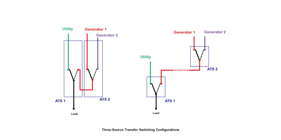
In the figure, the sketch at left shows two ATSs that would be installed in side-by-side enclosures with cable or bus interconnections. This is most common and offers a complete solution in a single installation. The sketch at right shows two separate ATSs connected by contractor-provided power cabling. This solution offers flexibility for locating ATSs. For facilities where a single generator and a single ATS are already present, retrofitting a second generator and a second ATS provides the same configuration.
Regardless of how the two switches are packaged, connection of three-source systems is identical.
- Generator 1 is connected to the Source 1 side of ATS 2
- Generator 2 is connected to the Source 2 side of ATS 2
- The load terminals of ATS 2 are connected to the Emergency side of ATS 1
- Utility service is connected to the Normal side of ATS 1
- Loads are always served by ATS 1
In normal operation, utility provides power to the Normal side of ATS 1, which is directed to power distribution circuits. For many applications, when acceptable normal power is interrupted, the ATS controls will start both engine-generator sets. The first to produce acceptable voltage and frequency is selected by ATS 2, then ATS 1 closes on the emergency source. If the first gen-set operates properly, the other genset set is shut down after a pre-set run time. If the first genset subsequently fails, the second genset will be started and brought online. When normal power is restored, the load is retransferred to the utility service by ATS 1, and the generator is stopped after cool-down. On ASCO ATSs, controls can also be set to start either Generator 1 or Generator 2 first. If the selected unit fails to start or run, the remaining generator is started and brought online. Users can also set generators to alternate between runs to balance runtime between units.
In these setups, ATS 1 and ATS 2 have dedicated controllers. The controller for ATS 1 will typically be a standard model. The controller for ATS 2 may require accessories to execute dual-generator operation. These details can be addressed directly with the ATS manufacturer.
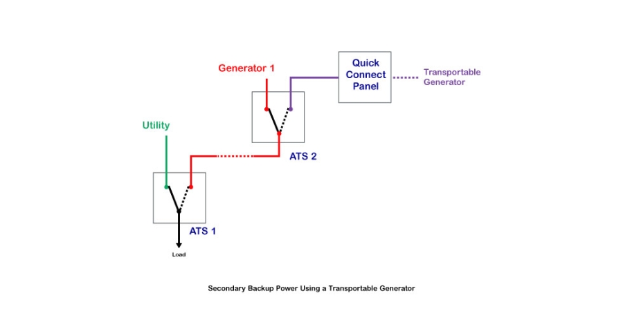
In ASCO’s experience, three-source transfer solutions are used across a wide range of industries and applications, wherever two generators are needed in an “n+1” configuration. Telecom facilities present a particularly interesting example, illustrated below. Cell site and landline switching facilities sometimes add a
quick-connect panel on ATS 2, then use a transportable generator to supply secondary backup power whenever needed. This equipment arrangement can make secondary backup power available to multiple facilities while reducing overall capital expense, and can be especially useful where
planned utility outages could occur.