Our Brands

My Documents 0

Welcome to the ASCO Website

Welcome to our website.

Managing Ground Faults in Backup Power Systems

Ground faults are unintended electrically conductive connections between an ungrounded conductor and normally noncurrent-carrying conductors, metallic objects such as enclosures, or earth. By energizing items that people can touch, they can create a safety hazard. When they subsist at levels below the fusing current, they can also create a fire hazard.

Article 230.95 of the National Electrical Code® requires ground fault sensing systems on electrical services exceeding 1000 Amps, 150 to 600 Volts. This article summarizes some common considerations for mitigating ground faults in backup power systems.

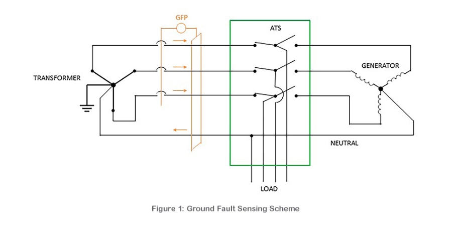
Ground fault sensing systems monitor whether the amount of current flowing into a circuit through phase conductors matches the amount of current flowing out (Figure 1).
When it doesn’t, phase current may be faulting to ground somewhere along the circuit. When the fault exceeds the set pickup level of a ground fault sensor, the ground fault sensing equipment signals a breaker to open to stop current flow (Figure 2).
Implementing ground fault protection requires consideration of the available current pathways when faults occur. The following sections give a few examples.

If a generator set is not properly grounded, it could cause nuisance tripping of the of the Normal source circuit breaker even though there is no current flowing through it. If the fault occurred between the generator and the transfer switch, it could trip the normal source breaker, preventing both isolation of the fault and retransfer to the Normal source (Figure 3).
If a generator set is provided with a dedicated ground (without other provisions), ground current could divide among two paths. If the current flow back to the generator ground is sufficiently large, ground fault protection will not operate.
A fundamental solution is to isolate the neutral by adding a fourth pole to the transfer switch, an a dedicated ground to the alternate power source. If a ground fault occurs, it cannot pass through the neutral of the opposing power source to cause ground fault sensing issues.
Note that where the three-phase four-wire load is small relative to the rest of the load, it may be less costly to use three-pole transfer switches and install a delta-wye isolation transformer between the transfer switch and the four-wire load. Nevertheless, this solution does not provide ground fault protection on the secondary side of the isolation transformer.

Another application involves providing overlapping neutral contacts. When current is flowing on the neutral, momentary interruption of the neutral can cause nuisance tripping of downstream equipment and overvoltages that could affect the service life of sensitive digital load equipment. Overlapping neutral contacts connect the two grounding conductors only during transfer and retransfer, isolating them at other times (Figure 6).
Summary

Approaches for managing ground faults are best selected based on the application, the corresponding code requirements, available pathways from ground fault current flow, and available switch solutions that can isolate power source neutrals. The use cases above illustrate some basic ground fault concerns and strategies. Contact switchgear manufacturers and qualified engineers to obtain support for selecting the best approach for specific applications.

Get the latest white papers, product news and insights straight to your inbox

Subscribe Now