Our Brands

My Documents 0

Welcome to the ASCO Website

Welcome to our website.

Engine Start Monitoring Overview

Since 2017, facilities with backup power systems have been subject to requirements to monitor the integrity of engine-generator start signal wiring. The following article explains why the National Electrical Code (NEC) added this requirement and differentiates approaches for compliance.

The Need for Monitoring

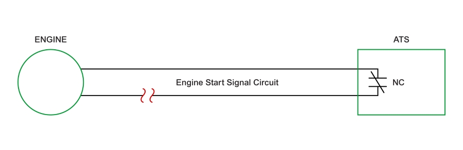
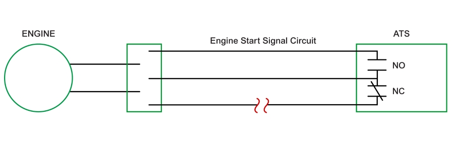
Connecting an engine-generator to a building’s electrical system through an Automatic Transfer Switch (ATS) is among the most common backup power system configurations. When the transfer switch detects unacceptable power or an outage on its primary power source, it signals the engine to start through the control wiring, then transfers load to the genset after it produces acceptable power.

If the start signal wiring becomes compromised, the engine may not start, resulting in an outage of the backup power system. This can occur because of a malfunction such as an open fault from a loose connection, a damaged wire, or a cable cut.

To avoid problems, a requirement to monitor engine start signal circuits was added to the 2017 Edition of the NEC. The requirement reads:

700.10(D)(4) Generator Control Wiring.

Control conductors installed between the transfer equipment and the emergency generator shall be kept entirely independent of all other wiring and shall meet the conditions of 700.10(D)(2). The integrity of the generator remote start circuit shall be monitored for broken, disconnected, or shorted wires. Loss of integrity shall start the generator(s).

Approaches to Compliance

One approach to complying with the NEC requirement is to use a three-wire solution for monitoring signal circuit integrity. This involves using a normally open and a normally closed contact between the wire pairs. If the systems operate properly, the contacts will be in opposite states. If the contacts are in the same state, a signaling problem is present that could result in an outage.

Potential problems with this approach include situations where circuit problems may not be detected. For instance, an open circuit where shown below may not be recognized by a normally closed contact. The problem would remain undetected until the genset is needed to supply backup power. Without immediate notification, users will not know to investigate the cause and extent of the issue. For multiple switch applications, this 3-wire solution does not show where faults occur.

An alternate solution is to route a two-wire engine start signal circuit through electronic components that can immediately detect fault conditions, a solution shown below. Using this approach, the electronic components can recognize an open or a short, then immediately annunciate the condition and start the genset, a solution that can help resolve the condition more quickly while avoiding a backup system outage.
In addition to offering continuous monitoring, this approach can be used on conventional two-wire start circuits. As a result, it is easy to deploy on new systems and can readily be retrofitted to existing systems. In multi-switch applications, this solution can also identify which circuit is the origin of the fault.

This article compares two approaches for complying with the NEC engine start monitoring requirement. For additional information on this subject, refer to the ASCO White Paper entitled Monitoring the Integrity of Engine Start Signal Circuits. Readers can attend ASCO’s July 28 webinar on the Fundamentals of Manual Switches, Docking Stations and Generator Engine Start Monitoring by registering at https://www.ascopower.com/us/en/resources/asco-innovation-webinars/manual-switch-fundamentals-28-7-2020.jsp. The 60-minute webinar is free-of-charge, and attendees can earn continuing education credits.

Get the latest white papers, product news and insights straight to your inbox

Subscribe Now